0900766b8171bf63.pdf - 第16页
16 MY(S) Dimensions (Unit: mm) Safety Precautions Refer to the Common Relay Precautions . Applicable Sockets Use only combinations of OMRON Relays and Sockets. 28 max. 6.3 2.6 0.5 21.5 max. 0.5 36 max. 6.4 Fourteen, 1.2-…
MY(S)
15
Miniature Power Relays: MY4Z-CBG
Specifications
Contact Ratings Characteristics
Note: The above values are initial values.
*1. Measurement conditions: 1 A at 5 VDC using the voltage drop method
*2. Measurement conditions: With rated operating power applied, not including
contact bounce.
Ambient temperature condition: 23° C
*3. Measurement conditions: For 500 VDC applied to the same location as for
dielectric strength measurement.
*4. Ambient temperature condition: 23° C
*5. This value was measured at a switching frequency of 120 operations per
minute.
Engineering Data
Load
Item
Resistive load
Inductive load
(cos φ = 0.4, L/R = 7 ms)
Rated load
1 A at 220 VAC
1 A at 24 VDC
0.3 A at 220 VAC
0.5 A at 24 VDC
Rated carry
current
1 A
Maximum contact
voltage
250 VAC, 125 VDC
Maximum contact
current
1 A
Contact form 4PDT (Crossbar bifurcated)
Contact materials Au cladding + AgPd
Contact resistance
*1
100 mΩ max.
Operation time
*2
20 ms max.
Release time
*2
20 ms max.
Maximum
operating
frequency
Mechanical 18,000 operations/h
Electrical 1,800 operations/h
Insulation resistance
*3
100 MΩ
Dielectric
strength
Between coil
and contacts
2,000 VAC at 50/60 Hz for 1 min.
Between contacts
of different polarity
Between contacts
of the same polarity
700 VAC at 50/60 Hz for 1 min.
Vibration
resistance
Destruction
10 to 55 to 10 Hz, 0.5-mm single amplitude
(1.0-mm double amplitude)
Malfunction
10 to 55 to 10 Hz, 0.5-mm single amplitude
(1.0-mm double amplitude)
Shock
resistance
Destruction 1,000 m/s
2
Malfunction 200 m/s
2
Endurance
Mechanical
5,000,000 operations min. (operating
frequency: 18,000 operations/hr)
Electrical
*4
50,000 operations min. (switching
frequency: 1,800 operations/h) at rated load
Failure rate P value (reference value)
*
5
100 μA at 1 VDC
Ambient operating temperature
−
25 to 70°C (with no icing or condensation)
Ambient operating humidity 5% to 85%
Weight Approx. 35 g
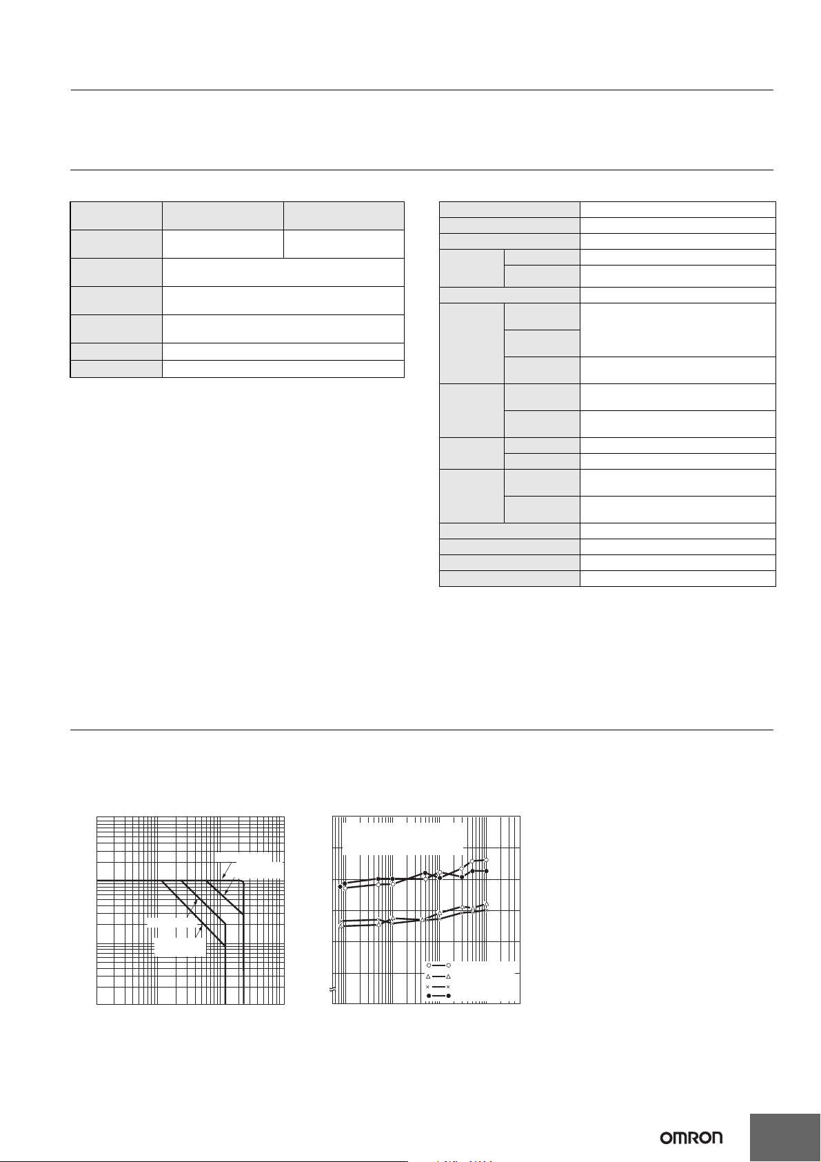
Maximum Switching Capacity Contact Reliability Test
(Modified Allen Bradley Circuit)
MY4Z-CBG
Contact load: 5 VDC, 1 mA resistive load
Malfunction criteria level: Contact resistance of 100 Ω
10
0.01
0.05
0.1
0.5
1
5
1 5 10 50 100 500
Contact voltage (V)
Contact current (A)
DC inductive load
(L/R = 7 ms)
DC resistive load
AC resistive load
AC inductive load
(cos φ = 0.4)
0
20
22
24
26
28
30
1 5 10 50 100 500 1,000
Number of operations (×10
4
operations)
Contact resistance (mΩ)
Number of Relays: 10 (average value)
Current-carrying contact
Open contacts
Self-latching contacts
Closed contacts
Malfunction rate: λ
60
= 0.0046 × 10
-6
per operation
(switching frequency: 200 operations/ min.)
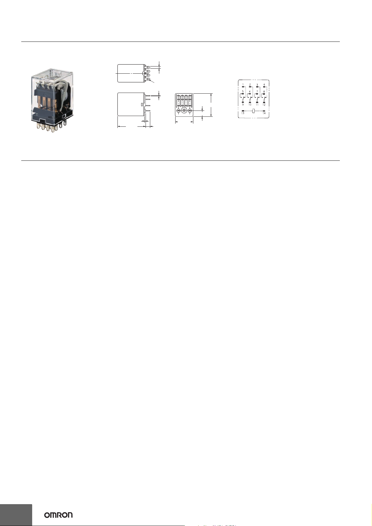
16
MY(S)
Dimensions (Unit: mm)
Safety Precautions
Refer to the Common Relay Precautions.
Applicable Sockets
Use only combinations of OMRON Relays and Sockets.
28 max.
6.3
2.6
0.5
21.5 max.
0.5
36 max.
6.4
Fourteen, 1.2-dia. × 2.2 oval holes
MY4Z-CBG
Terminal Arrangement/Internal
Connections (Bottom View)
Standard Models
(The coil has no polarity.)
MY(S)
17
Plastic Sealed Relays: MYQ4
Specifications
Contact Ratings
* This value was measured at a switching frequency of 120 operations per minute.
* With no icing or condensation.
Characteristics
Engineering Data
Type
Item
Resistive load
Inductive load
(cos φ = 0.4, L/R = 7 ms)
Rated load 1 A at 220 VAC, 1 A at 24 VDC 0.5 A at 220 VAC, 0.5 A at 24 VDC
Rated carry current 1 A
Maximum contact voltage 250 VAC, 125 VDC
Maximum contact current 1 A
Maximum switching capacity
(reference value)
220 VAC, 24 W 110 VAC, 12 W
Failure rate P value
(reference value)
Single contacts: 1 mA at 1 VDC, Bifurcated contacts: 100 μA at 1 VDC
Contact form 4PDT, 4PDT (Bifurcated)
Contact materials Au plating + Ag
Ambient operating temperature −55 to 60° C
*
Ambient operating humidity 5% to 85%
Contact resistance
*1
50 m
Ω
max.
Note: The values at the left are initial
values.
*1. Measurement conditions: 1 A at 5
VDC using the voltage drop
method
*2. Measurement conditions: With
rated operating power applied, not
including contact bounce.
Ambient temperature condition:
23° C
*3. Measurement conditions: For 500
VDC applied to the same location
as for dielectric strength
measurement.
*4. This value is for bifurcated
contacts.
*5. Ambient temperature condition:
23° C
Operation time
*2
20 ms max.
Release time
*2
20 ms max.
Maximum
operating
frequency
Mechanical
18,000 operations/h
Rated load
1,800 operations/h
Dielectric
strength
Between coil and contacts
1,500 VAC at 50/60 Hz for 1 min.
Between contacts of different polarity
1,500 VAC at 50/60 Hz for 1 min.
Between contacts of the same polarity
1,000 VAC at 50/60 Hz for 1 min.
Insulation resistance
*
3
100 M
Ω
min.
Vibration
resistance
Destruction
10 to 55 to 10 Hz, 0.5-mm single amplitude (1.0-mm double amplitude)
Malfunction
10 to 55 to 10 Hz, 0.5-mm single amplitude (1.0-mm double amplitude)
Shock
resistance
Destruction
1,000 m/s
2
Malfunction
200 m/s
2
Endurance
Mechanical
AC: 50,000,000 operations (5,000,000
*
4
) min., DC: 100,000,000 operations
(5,000,000
*4
) min. (switching frequency: 18,000 operations/h)
Electrical
*
5
200,000 operations min. (100,000 operations
*4
) (rated load, switching
frequency: 1,800 operations/h)
Weight
Approx. 35 g
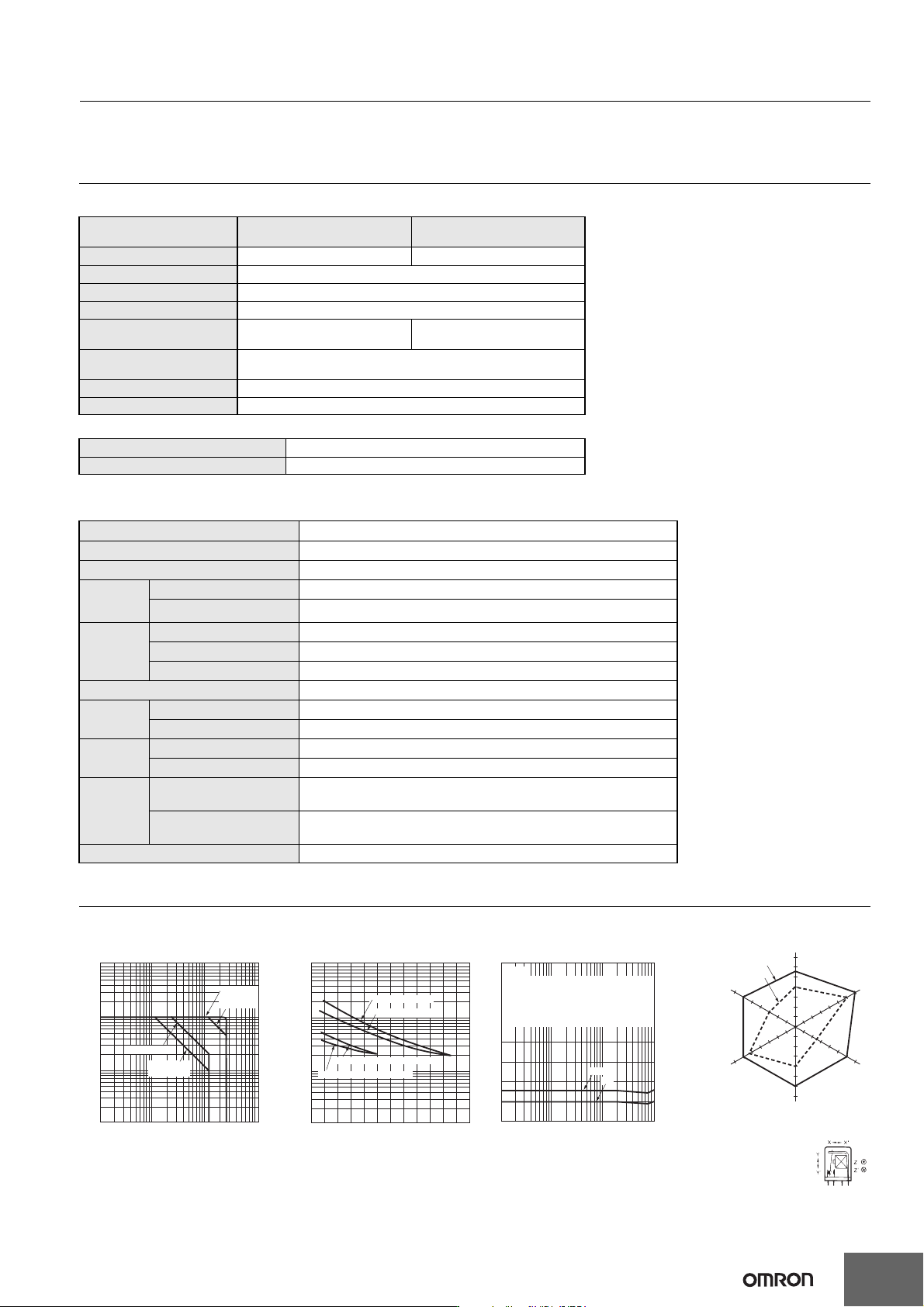
Maximum Switching Capacity Endurance Curve H
2
S Gas Data Malfunctioning Shock
MYQ4(Z) MYQ4 MYQ4
Energized
Y
X
Z
X’
Z’
Y’
550
400
600
300
550
600
400
600
600
250
600
700
Unit: m/s
2
Not energized
N = 20
Measurement: Shock was applied
3 times each in 6 directions along
3 axes with the Relay energized
and not energized to check the
shock values that cause the Relay
to malfunction.
Criteria: Non-energized: 200 m/s
2
Energized: 200 m/s
2
Shock
direction
DC inductive load
(L/R = 7 ms)
DC resistive load
AC resistive load
AC inductive load
(cos φ = 0.4)
10
0.01
0.03
0.05
0.07
0.1
0.5
0.3
0.7
1
3
7
5
15310 5030 100 500 1,000300
Contact voltage (V)
Contact current (A)
24 VDC resistive load
24 VDC inductive load (L/R = 7 ms)
220 VAC resistive load
220 VAC inductive load (cos φ = 0.4)
1
3
5
7
10
30
50
70
100
300
500
700
1,000
0 0.4 0.6 0.8 1.00.2 1.2
Contact current (A)
Number of operations (×10
4
operations)
Note: The durability of bifurcated
contacts is one-half that of
single contacts.
max.
N=10
min.
Measurements: Temperature: 40° C, Humidity: 60% to 70%,
H
2
S concentration: 5 ±3 ppm
The change in contact resistance was measured after
leaving the Relay in the above environment for a fixed
amount of time, then removing it to a constant-temperature
and constant-humidity environment for at least 30 minutes.
80
70
60
50
40
30
20
10
1
15310 5030 100 500 1,000300
Standing time (h)
Contact resistance (mΩ)