0900766b8171bf63.pdf - 第27页
MY(S) 27 Dimensions (Unit: mm) Note: All units are in millimeters unless otherwise indicated. Socket Dimensions Terminal arrangement/ Internal connections (top view) Mounting holes PYF-08-PU (4.2) (4.2) 90 31 67.5 52.1 2…
26
MY(S)
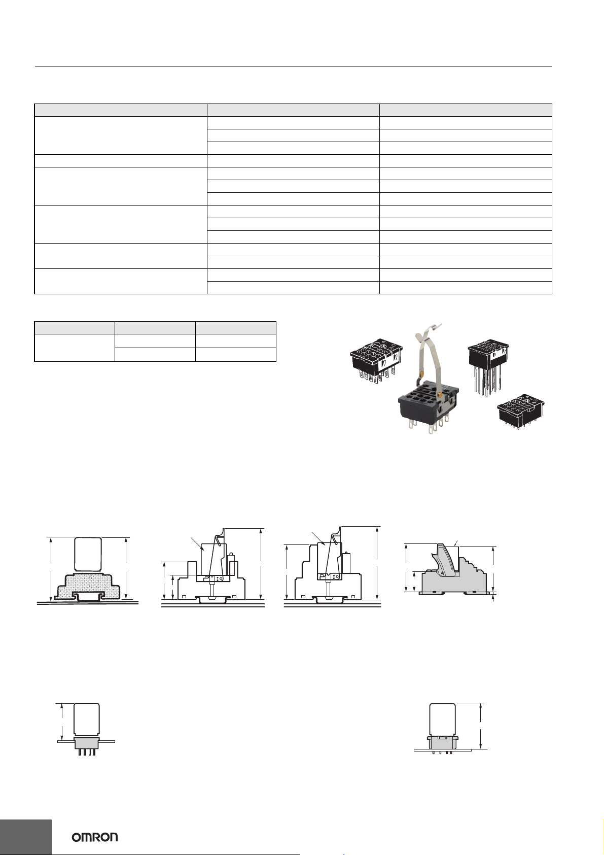
Safety Standards for Sockets
Front-mounted Sockets (PYF@)
Back-connecting Sockets (PY@)
Mounting Heights with Sockets (Unit: mm)
Model Standards File No.
PYF-08-PU
PYF-14-PU
TÜV (EN 61984) ---
UL508 E87929
CSA C22.2 No.14 ---
PYF14A-E, PYF14A-N VDE0627 (EN61984) Nr.B387 (License No.)
PYFZ-08-E
PYFZ-14-E
TÜV(EN 61984) R50405329
UL508 E87929
CSA22.2 LR31928
PYF08A-E, PYF08A-N
PYF14A-E, PYF14A-N
TÜV(EN 61984) J50224549
UL508 E87929
CSA22.2 LR31928
PYF14-ESN-B
PFY14-ESS-B
UL508 E244189
CSA22.2 LR225761
PYF08A
PFY14A
UL508 E87929
CSA22.2 LR31928
Model Standards File No.
PY08(-02)
PY14(-02)
UL508 E87929
CSA C22.2 LR31928
Front-mounting Sockets
Screw terminal
(PYF@A (-E), PYF
@
A-N, PYF14-ES
@
-B)
Push-In Plus Terminal Block Sockets
(PYF-
@
-PU)
Back-mounting Sockets
Solder terminals/Wrapping terminals
(PY
@
)
Relays with PCB Terminals
(PY
@
-02)
MY
PYFZ-@-E
PYF@A-(@)
66 (83)70 (87)
Note: 1.
The PYF
@
A can be mounted on a track or with screws.
2.
The heights given in parentheses are the measurements
for 53-mm-high Relays.
80
42.5
27
PYF14-ESN-B
MY
82
61
PYF14-ESS-B
MY
(3.9)
28.1
67.5
63.1
MY
PYF-@-PU
39 (56)
MY
PY@
MY
48.2
PY@-02
MY(S)
27
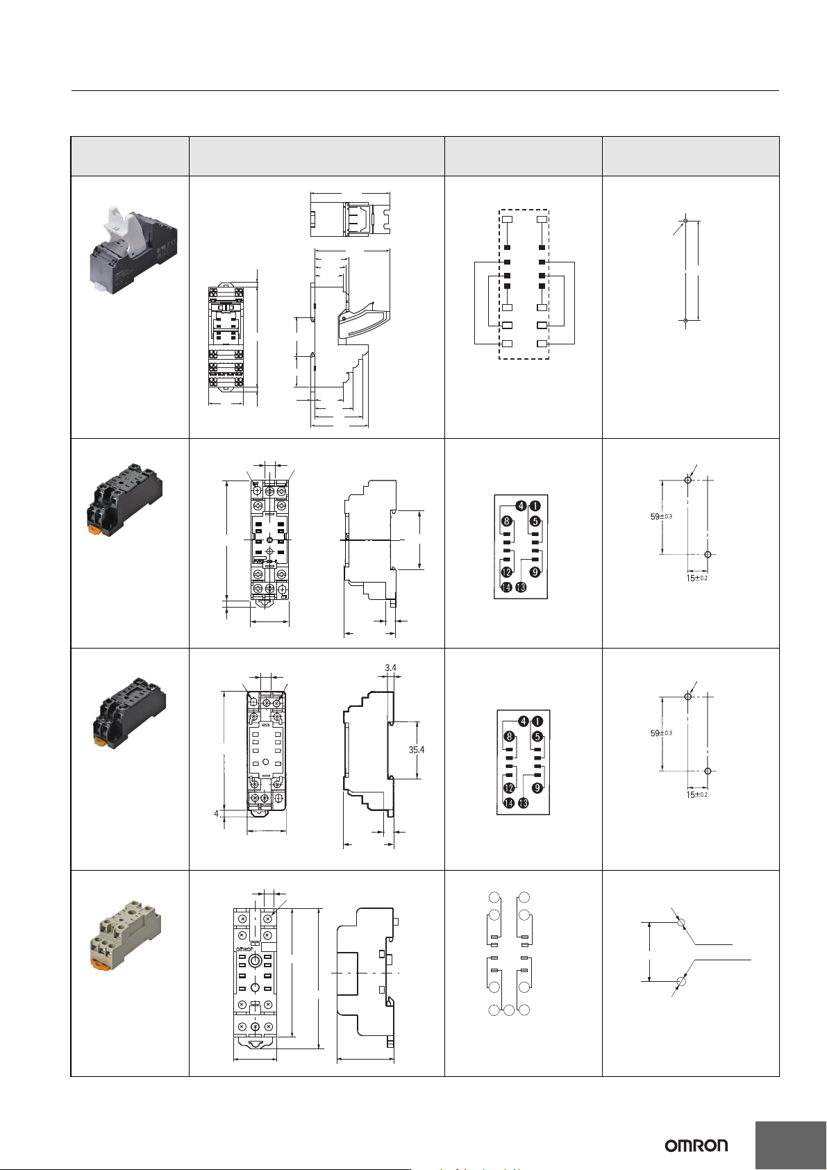
Dimensions (Unit: mm)
Note: All units are in millimeters unless otherwise indicated.
Socket Dimensions
Terminal arrangement/
Internal connections
(top view)
Mounting holes
PYF-08-PU
(4.2)
(4.2)
90
31
67.5
52.1
25.6
30.8
28.1
35.3
27.35
25.6
34.3
43
3.9
71.5
(13)
(1) (4)
(5) (8)
(9) (12)
(14)
14
42
44
41
12
11
A2A1
Note: The numbers in
parentheses are
traditionally used
terminal numbers.
Two M3 screw
holes or
two 3.5-dia. holes
108
Note 1: Pull out the hooks
to mount the Socket
with screws.
Note 2: DIN-rail mounting is also
possible. Refer to page 34
for supporting DIN-rails.
PYFZ-08-E
35.4
6
31 max.
23 max.
4
72 max.
Two, 4.2 × 5
mounting
holes
6
+0.2
−0.1
Eight, M3 × 8
(TOP VIEW)
Two, M3, M4, or 4.5-dia. holes
Note: DIN-rail mounting is also
possible. Refer to page 34
for supporting DIN-rails.
PYF08A-E
23 max.
72 max.
Two, 4.2 x 5
mounting
holes
Eight, M3 x 8
6
31 max.
6
+0.2
−0.1
(TOP VIEW)
Two, M3, M4, or 4.5-dia. holes
Note: DIN-rail mounting is also
possible. Refer to page 34
for supporting DIN-rails.
PYF08A-N
4
42
8
44
1
12
5
14
41
12
A2
14
11
9
A1
13
A2
14
PYF-08A-N
73
22 max.
67 max.
30 max.
Eight, M3×8
6
+0.2
−0.1
4
42
1
8
5
12 9
14
14
13
44
12
14
41 11
A2 A2 A1
Note: Figures in parentheses
indicate DIN standard
numbers.
18.7
3.0 dia.
3.5 dia. or M3
Note: DIN-rail mounting is also
possible. Refer to page 34
for supporting DIN-rails.
28
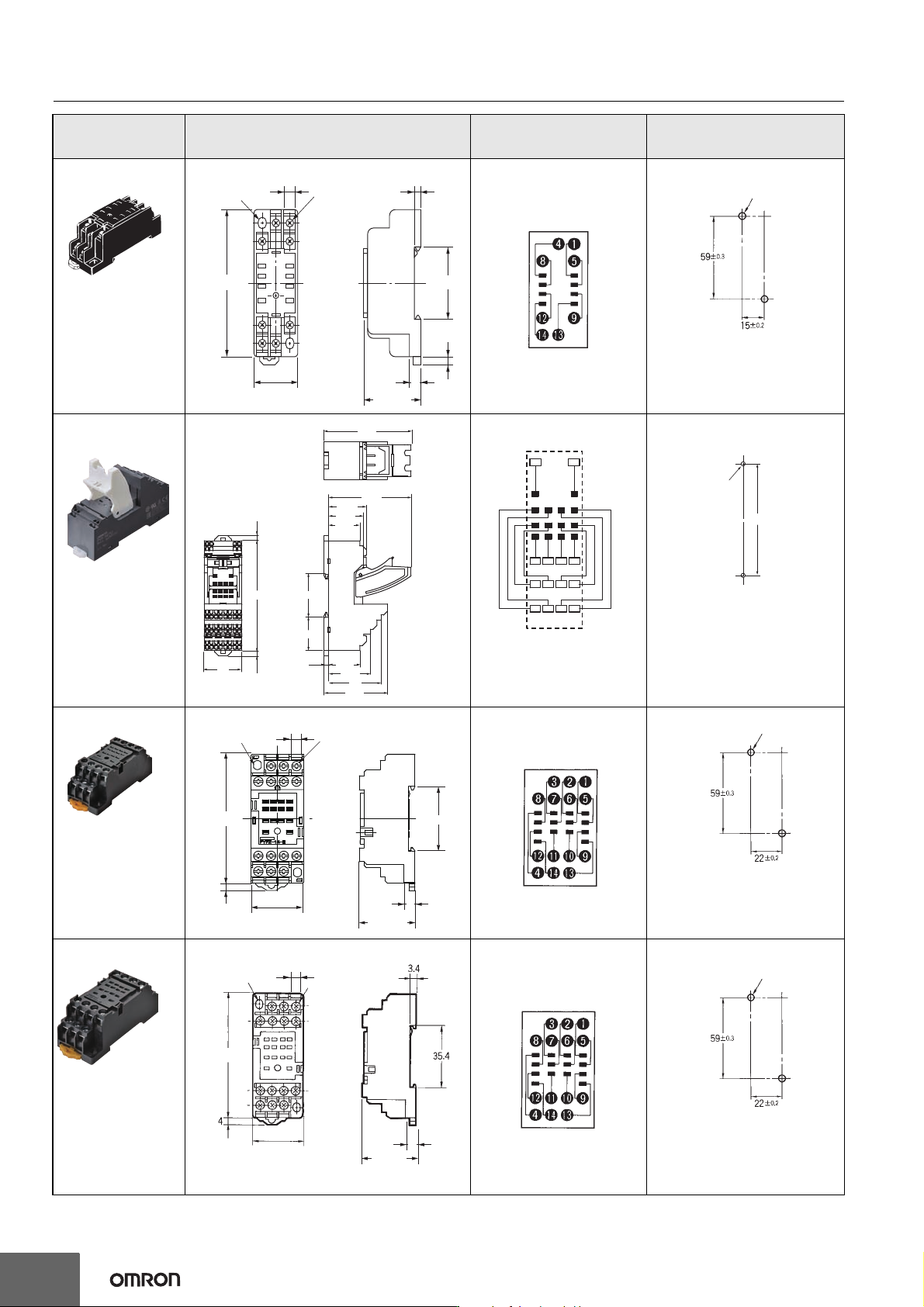
MY(S)
Socket Dimensions
Terminal arrangement/
Internal connections
(top view)
Mounting holes
PYF08A
30 max.
6
4
35.4
3.4
23 max.
72 max.
6
+0.2
−0.1
Eight, M3×8
Two, 4.2 × 5
mounting holes
(TOP VIEW)
Two, M3, M4, or 4.5-dia. holes
Note: DIN-rail mounting is also
possible. Refer to page 34
for supporting DIN-rails.
PYF-14-PU
(4.2)
(4.2)
90
31
43
34.3
25.6
3.9
35.3
27.35
25.6
28.1
30.8
67.5
71.5
52.1
14
423222
443424
413121
12
11
A2A1
(13)
(1) (2) (3) (4)
(5) (6) (7) (8)
(9)
(10) (11) (12)
(14)
Note: The numbers in
parentheses are
traditionally used
terminal numbers.
Two M3 screw
holes or
two 3.5-dia. holes
108
Note 1: Pull out the hooks
to mount the Socket
with screws.
Note 2: DIN-rail mounting is also
possible. Refer to page 34
for supporting DIN-rails.
PYFZ-14-E
35.4
6
4
31 max.
29.5 max.
72 max.
Two, 4.2 x 5
mounting
holes
Fourteen, M3 x 8
sems screws
6
+0.2
−0.1
(TOP VIEW)
Two, M3, M4, or 4.5-dia. holes
Note: DIN-rail mounting is also
possible. Refer to page 34
for supporting DIN-rails.
PYF14A-E
29.5 max.
72 max.
Two, 4.2 x 5
mounting
holes
Fourteen, M3 x 8
sems screws
6
31 max.
6
+0.2
−0.1
(TOP VIEW)
Two, M3, M4, or 4.5-dia. holes
Note: DIN-rail mounting is also
possible. Refer to page 34
for supporting DIN-rails.