0900766b8171bf63.pdf - 第33页
MY(S) 33 Safety Precautions Maximum Carry Current • Do not allow the total current for all shorted contact for m to exceed the maximum carry current of the Short Bar. • Do not exceed the maximum carry current of t he rel…
32
MY(S)
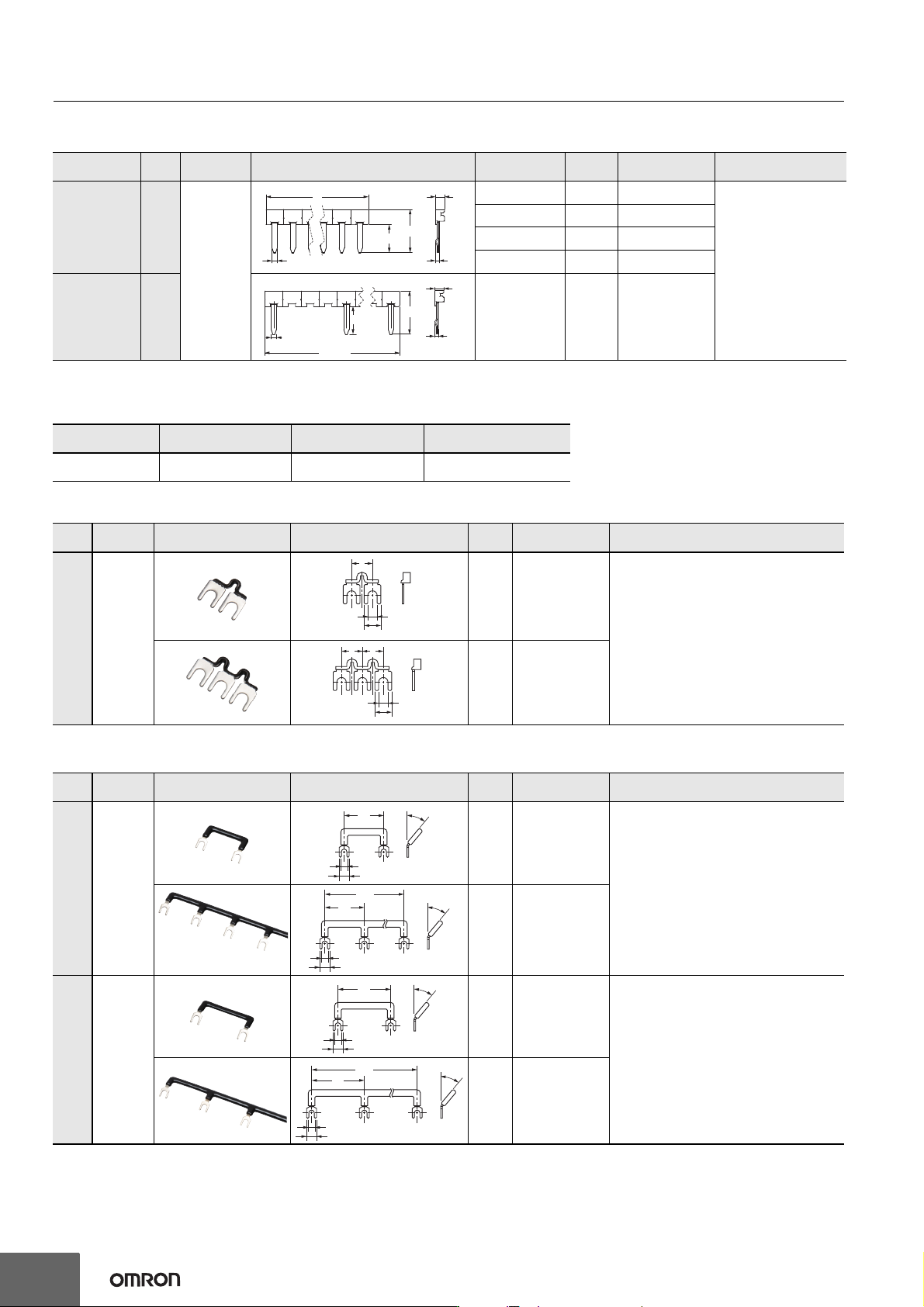
Short Bars for Relay Sockets and PYF Sockets
Short Bars for crossover wiring within one Socket or between Sockets
* Replace the box (@) in the model number with the specification code for the covering color. B: Black, S: Blue, R: Red
Note: When using short bar to coil terminals of PYF-@@-PU, make sure to use PYDN-31.0-080@ (31mm).
Labels
Note: PRINTER: MARKINGENIUS MG3 (Ask to your Omron contact for more details on printers)
Short Bars for within the Same Socket
* Replace the box (@) in the model number with the specification code for the covering color. B: Black, Y: Yellow
Short Bars for Adjacent Sockets
* Replace the box (@) in the model number with the specification code for the covering color. B: Black, S: Blue, R: Red
Application
Pitch
Applicable
model
Appearance and dimensions (mm) L (Length)
No. of
poles
Model * Specifications
For Contact
terminals
(common)
7.75
mm
PYF-@-PU
15.1 2 PYDN-7.75-020@
Max. carry current: 20 A
Minimum order: 10
22.85 3 PYDN-7.75-030@
30.6 4 PYDN-7.75-040@
154.6 20 PYDN-7.75-200@
For Coil
terminals
31.0
mm
224.35 8 PYDN-31.0-080@
Applicable sockets Model Manufacturer
Minimum order (Box)
(quantity per box)
PYF-08-PU(-L)
PYF-14PU(-L)
MG-CPM-04 41390N Cembre
1,680
(35 sheet / 48 pieces)
Pitch
Applicable
model
Appearance Dimensions (mm)
No. of
poles
Model * Specifications
7
mm
PYF14A
2
PYD-020B@
Max. carry current: 20 A (18 A at 70°C)
Ambient operating temp.: -40 to 70°C (with no
icing or condensation)
Ambient operating humidity: 45% to 85% (with
no icing or condensation)
Conductor material: Brass
Conductor surface treatment: Nickel plating
Qty per package: 50/bag
3
PYD-030B@
Pitch
Applicable
model
Appearance Dimensions (mm)
No. of
poles
Model * Specifications
22
mm
PYF08A
2
PYD-025B@
Max. carry current: 20 A (18 A at 70°C)
Ambient operating temp.: -40 to 70°C (with no
icing or condensation)
Ambient operating humidity: 45% to 85% (with
no icing or condensation)
Conductor material: Brass
Conductor surface treatment: Nickel plating
Qty per package: 10/bag
8
PYD-085B@
29
mm
PYF14A
2
PYD-026B@
Max. carry current: 20 A (18 A at 70°C)
Ambient operating temp.: -40 to 70°C (with no
icing or condensation)
Ambient operating humidity: 45% to 85% (with
no icing or condensation)
Conductor material: Brass
Conductor surface treatment: Nickel plating
Qty per package: 10/bag
8
PYD-086B@
3.90
1.572.25
12
L
18.5
2.25
1.57
3.90
18.5
12
224.35
7
3.2
5.6
77
3.2
5.6
22
40°
3.3
5.6
22
154
40°
3.3
5.6
29
40°
3.3
5.6
29
203
40°
3.3
5.6
MY(S)
33
Safety Precautions
Maximum Carry Current
• Do not allow the total current for all shorted contact form to exceed the maximum carry current of the Short Bar.
• Do not exceed the maximum carry current of the relay contacts for individual contact form.
• If you use more than one Socket, use End Plates (PFP-M).
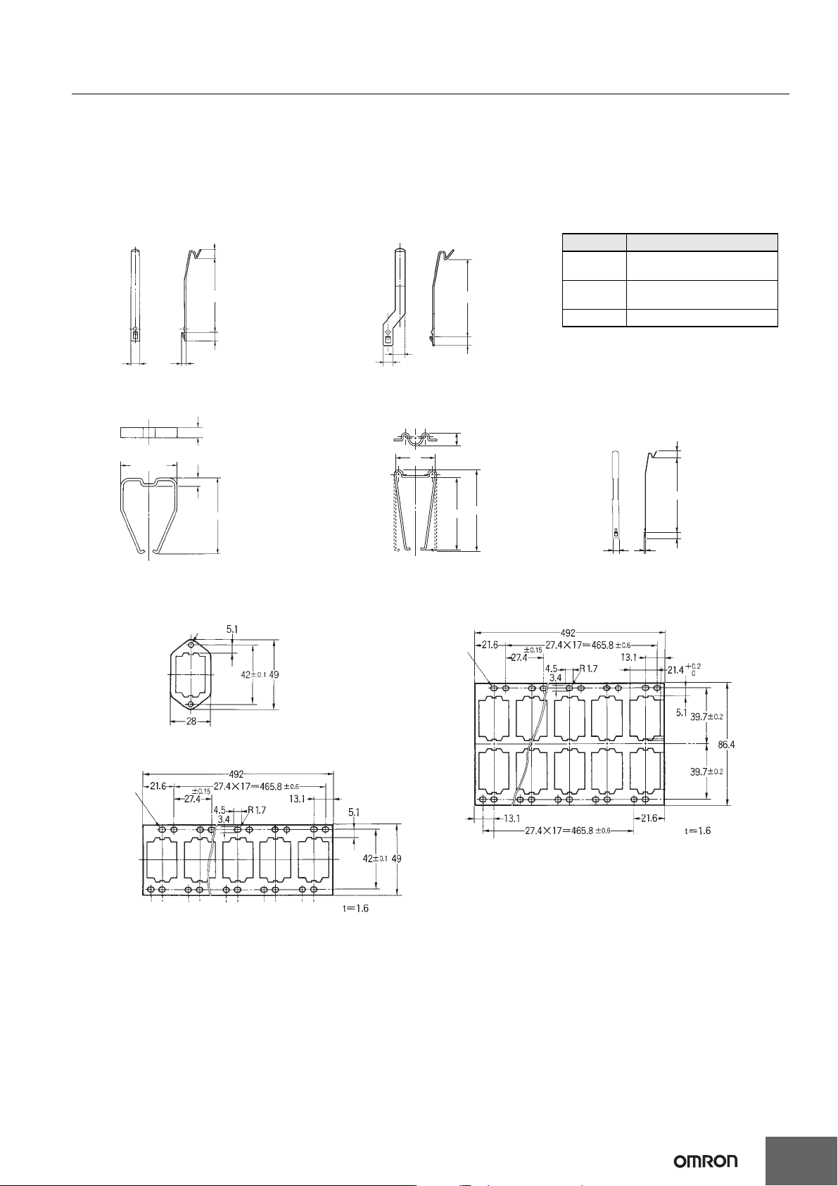
Hold-down Clips
Mounting Plates for Back-connecting Sockets
4.5
1.2
36.3
4.5
36.3
5.75
4.25
4.5
±0.1
5
3.3
38.5
53
5 max.
4.5
1.24.5
PYC-P PYC-1 Y92H-3
29 max.
PYC-A1
(2 pcs per set)
PYC-E1
(2 pcs per set)
9.4
52
28
58.2
For sockets PYF14-ESN/-ESS
Note: For total dimensions with plastic clip please
refer to drawings of the sockets.
Model Description
PYC-0
Metal spring clip (Used with
Relay only)
PYC 35
Plastic holding clip (Used with
Relay only)
PYC TR1 Thermoplastic writable label
PYP-1
PYP-36
PYP-18
t=1.6
Two, 3.4-dia. holes
72 elliptical holes
72 elliptical holes
34
MY(S)
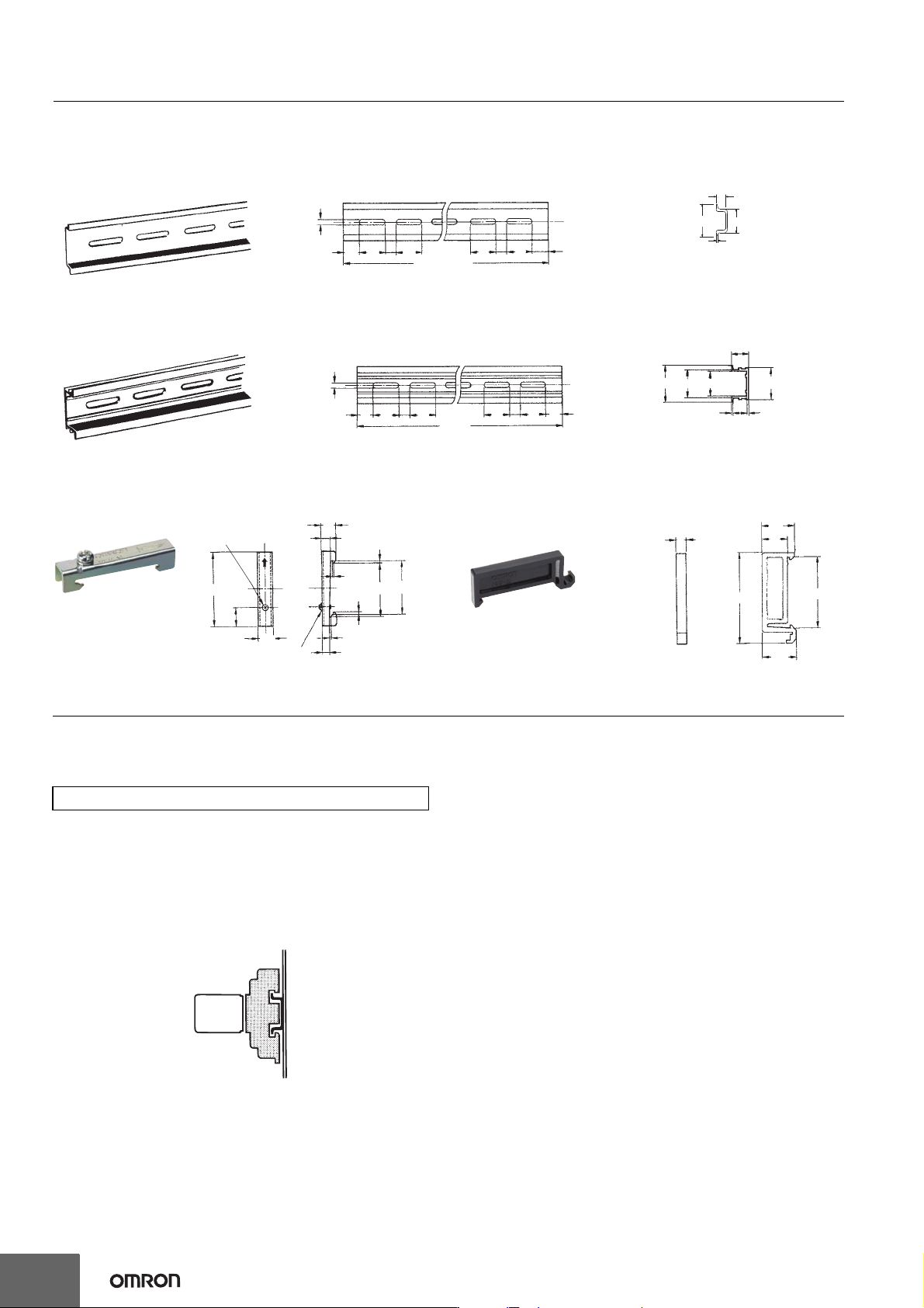
DIN-rails and Accessories
Supporting DIN-rails
PFP-50N/PFP-100N
PFP-100N2
End Plate
PFP-M
Spacer
PFP-S
Safety Precautions
Refer to the Common Relay Precautions.
Refer to Products Related to Common Sockets and DIN Tracks for precautions on the applicable Sockets.
Refer to PYF-
@@
-PU/P2RF-
@@
-PU for precautions on Push-In Plus Terminal Block Sockets.
Handling
For models with a built-in operation indicator, models with a built-in diode, or
high-sensitivity models, check the coil polarity when wiring and wire all
connections correctly (DC operation).
Installation
• There is no specifically required installation orientation, but make sure that
the Relays are installed so that the contacts are not subjected to vibration or
shock in their movement direction.
• Use two M3 screws to attach Flange-mounted models (MY@F) and tighten the
screws securely (tightening torque: 0.98 N•m).
Using MY-series Relays with Microloads with
Infrequent Operation
If any standard MY-series Relays (e.g., MY4) are used infrequently to switch
microloads, the contacts may become unstable and eventually result in poor
contact. In this case, we recommend using the MY4Z-CBG Series, which has
high contact reliability for microloads (Refer to page 15.)
About the Built-in Diode and CR Elements
The diode or CR element that are built into the Relay are designed to absorb
the reverse voltage from the Relay coil. If a large surge in voltage is applied to
the diode or CR element from an external source, the element will be destroyed.
If there is the possibility of large voltage surges that could be applied to the
elements from an external source, take any necessary surge absorption
measures.
Latching Levers
• Turn OFF the power supply when operating the latching lever. After you use
the latching lever always return it to its original state.
• Do not use the latching lever as a switch.
• The latching lever can be used for 100 operations min.
Relay Replacement
To replace the Relay, turn OFF the power supply to the load and Relay coil
sides to prevent unintended operation and possible electrical shock.
4.5
15
25 25
10
25
1000 (500) *
25
10
15 (5)
1
35±0.3
7.3±0.15
27±0.15
Note: The figure in the parentheses is for PFP-50N.
29.2
1.5
27 24
16
1
4.5
15
25
25
10
25
1000
25
10
15
35±0.3
50
11.5
10
10
6.2
1.8
1
35.5
35.3
1.8
1.3
4.8
M4 x 8 pan head screw
M4 spring washer
5
16
12
44.3
16.5
34.8
Precautions for Correct Use