0900766b8171bf63.pdf - 第23页
MY(S) 23 Sockets for MY DIN-rail-mounted (DIN-rail) Socket Conforms to VDE 0106, Part 100 • Snap into position along continuous sectio ns of any mounting DIN-ra il. • Facilitates sheet metal desig n by standardi zed moun…
MY(S)
22
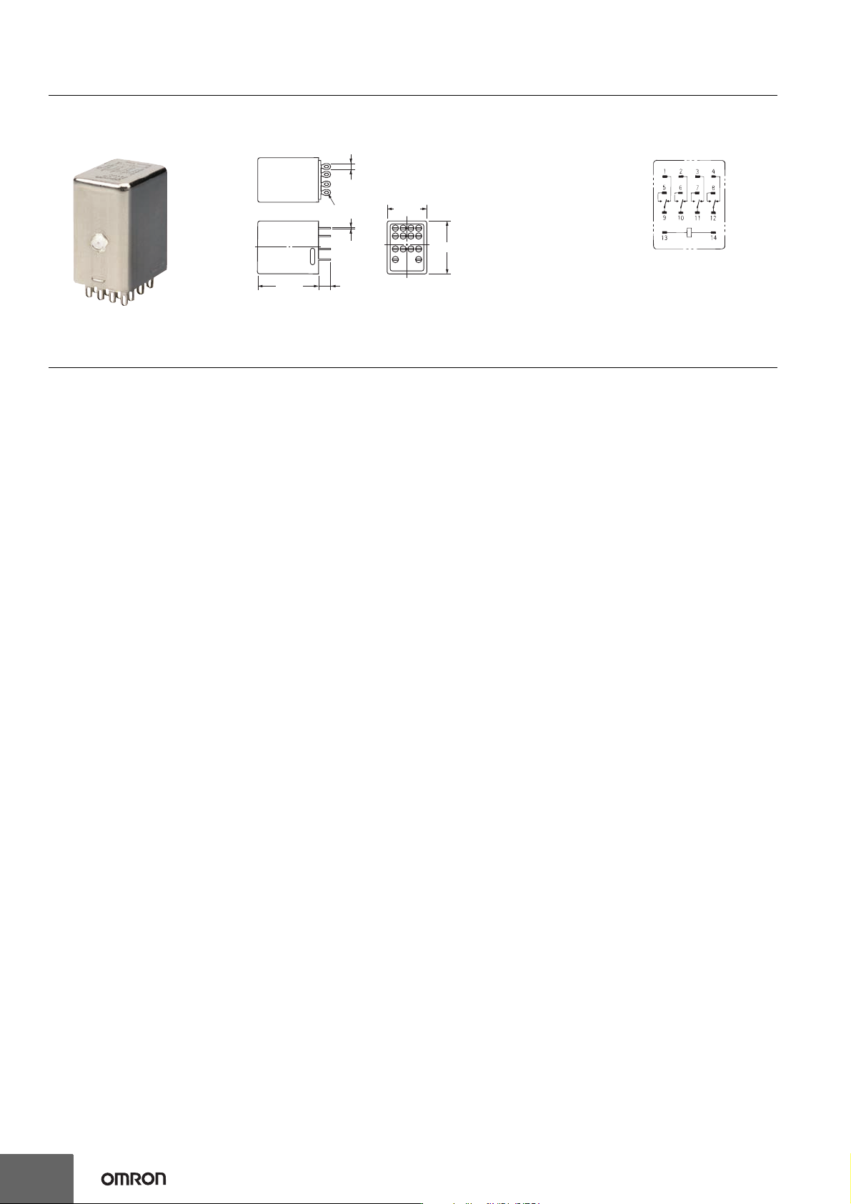
Dimensions (Unit: mm)
Safety Precautions
Applicable Sockets
Use only combinations of OMRON Relays and Sockets.
Application Environment for Hermetically Sealed
Relays
Humid environments can cause insulation problems, which may result in short-
circuiting or unintended operation.
Solution
Do not use these Relays in any environment where the Relay will come into
contact with water vapor, condensation, or water droplets. This can reduce the
surface tension of the insulating beads and cause short-circuiting or unintended
operation due to poor insulation.
Relay Replacement
To replace the Relay, turn OFF the power supply to the load and Relay coil
sides to prevent unintended operation and possible electrical shock.
28.5 max.
2.6
Fourteen, 1.2-dia. × 3 oval holes
35 max. 6.4
22 max.
0.5
Relays with Plug-in Terminals or Soldered Terminals
MY4(Z)H
Terminal Arrangement/
Internal Connections
(Bottom View)
(The coil has no polarity.)
MY(S)
23
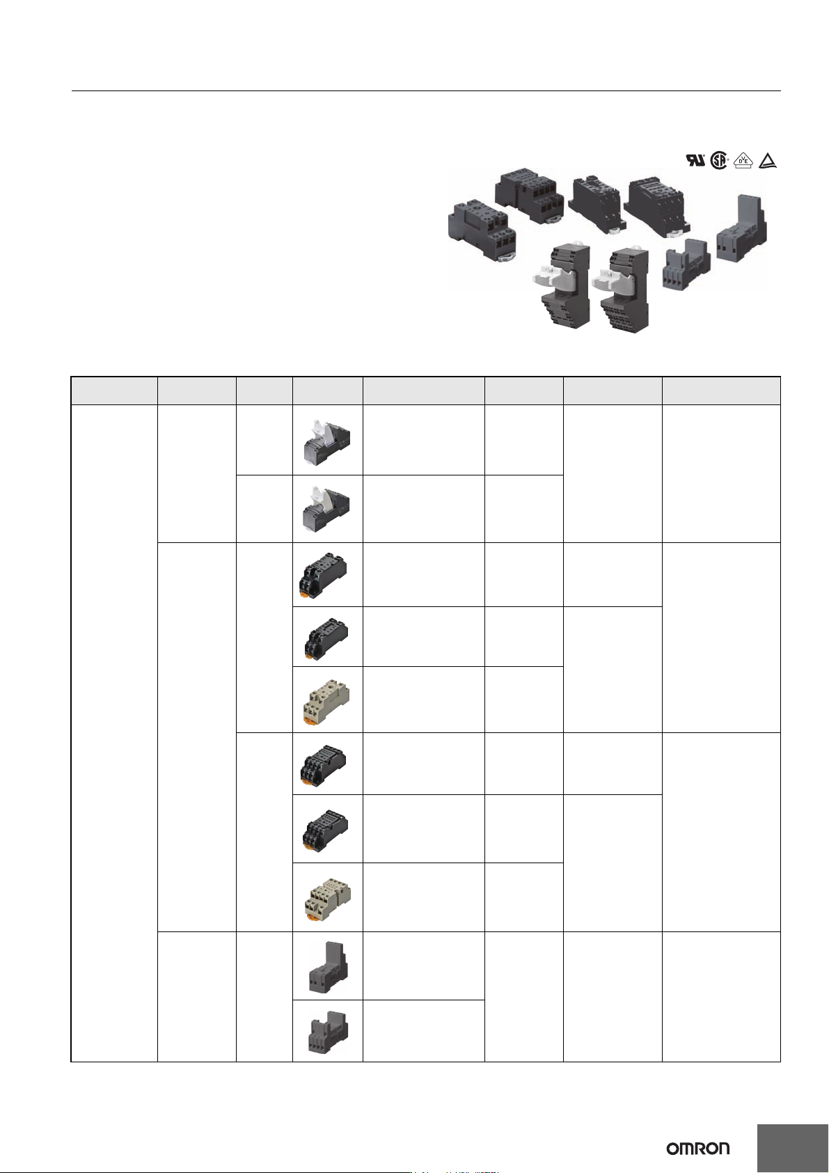
Sockets for MY
DIN-rail-mounted (DIN-rail) Socket
Conforms to VDE 0106, Part 100
• Snap into position along continuous sections of any
mounting DIN-rail.
• Facilitates sheet metal design by standardized mounting
dimensions.
• Design with sufficient dielectric separation between
terminals eliminates the need of any insulating sheet.
Specifications
Mounting
Terminal
type
No. of
poles
Appearance Model Carry current
Dielectric
withstand voltage
Insulation resistance
(see note 2)
DIN-rail-mounted
Socket
Push-In Plus
terminals
2 PYF-08-PU 10 A
2,000 VAC, 1 min 1,000 MΩ min
4 PYF-14-PU 6 A
Screw terminals
2
PYFZ-08-E 10 A 2,250 VAC, 1 min
1,000 MΩ min
PYF08A(-E) 7 A
2,000 VAC, 1 min
PYF08A-N (see note 3) 7 A (see note 4)
4
PYFZ-14-E 6 A 2,250 VAC, 1 min
1,000 MΩ min
PYF14A(-E) 5 A
2,000 VAC, 1 min
PYF14A-N (see note 3) 5 A (see note 4)
Rise-Up
terminals
2 and 4
Common
PYF14-ESS-B
12 A > 3 KV > 5 MΩ
PYF14-ESN-B
24
MY(S)
Note: 1. The values given above are initial values.
2. The values for insulation resistance were measured at 500 VDC at the same place as the dielectric strength.
3. The maximum operating ambient temperature for the PYF08A-N and PYF14A-N is 55°C.
4. When using the PYF08A-N or PYF14A-N at an operating ambient temperature exceeding 40°C, reduce the current to 60%.
5. The MY2(S) can be used at 70°C with a carry current of 7 A.
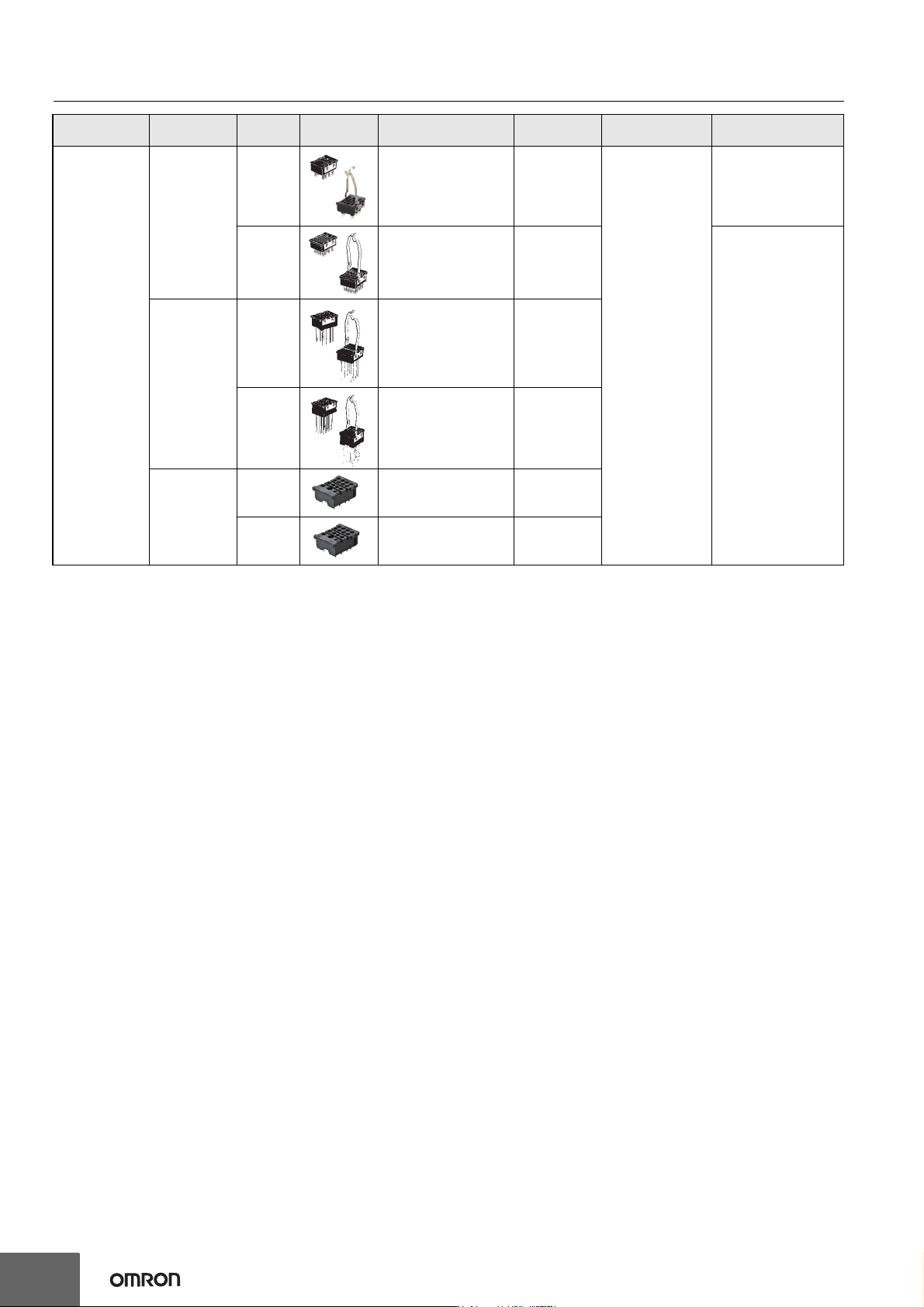
Back-connecting
Solder terminals
2 PY08(-Y1) 7 A
1,500 VAC, 1 min
1000 MΩ min.
4 PY14(-Y1) 3 A
100 MΩ min.
Wrapping
terminals
2 PY08QN(-Y1) 7 A
4 PY14QN(-Y1) 3 A
Relays with
PCB terminals
2 PY08-02 7 A
4 PY14-02 3 A
Mounting
Terminal
type
No. of
poles
Appearance Model Carry current
Dielectric
withstand voltage
Insulation resistance
(see note 2)