0900766b8171bf63.pdf - 第24页
24 MY(S) Note: 1. The values given a bove are initial val ues. 2. The values for insulation re sistance were measured at 500 VDC at t he same place as the dielectric stren gth. 3. The maximum operating ambient temperatur…
MY(S)
23
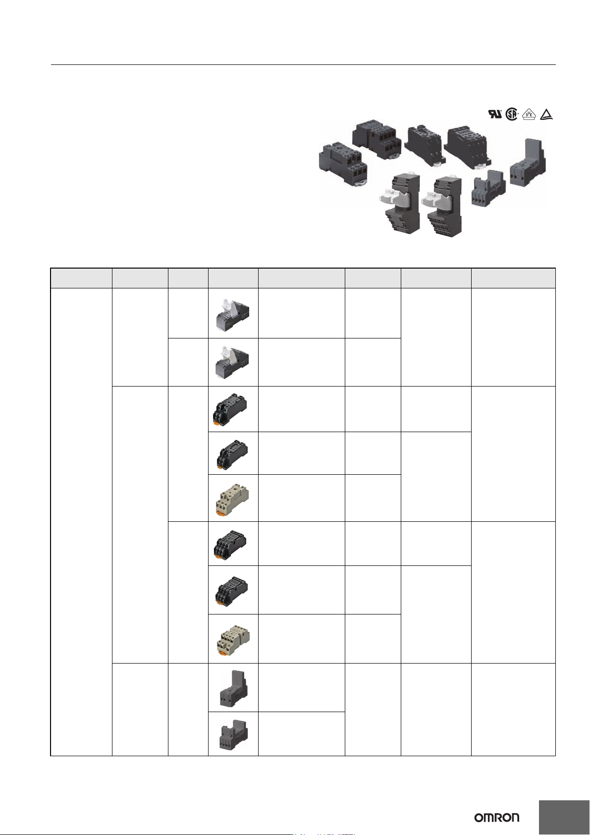
Sockets for MY
DIN-rail-mounted (DIN-rail) Socket
Conforms to VDE 0106, Part 100
• Snap into position along continuous sections of any
mounting DIN-rail.
• Facilitates sheet metal design by standardized mounting
dimensions.
• Design with sufficient dielectric separation between
terminals eliminates the need of any insulating sheet.
Specifications
Mounting
Terminal
type
No. of
poles
Appearance Model Carry current
Dielectric
withstand voltage
Insulation resistance
(see note 2)
DIN-rail-mounted
Socket
Push-In Plus
terminals
2 PYF-08-PU 10 A
2,000 VAC, 1 min 1,000 MΩ min
4 PYF-14-PU 6 A
Screw terminals
2
PYFZ-08-E 10 A 2,250 VAC, 1 min
1,000 MΩ min
PYF08A(-E) 7 A
2,000 VAC, 1 min
PYF08A-N (see note 3) 7 A (see note 4)
4
PYFZ-14-E 6 A 2,250 VAC, 1 min
1,000 MΩ min
PYF14A(-E) 5 A
2,000 VAC, 1 min
PYF14A-N (see note 3) 5 A (see note 4)
Rise-Up
terminals
2 and 4
Common
PYF14-ESS-B
12 A > 3 KV > 5 MΩ
PYF14-ESN-B
24
MY(S)
Note: 1. The values given above are initial values.
2. The values for insulation resistance were measured at 500 VDC at the same place as the dielectric strength.
3. The maximum operating ambient temperature for the PYF08A-N and PYF14A-N is 55°C.
4. When using the PYF08A-N or PYF14A-N at an operating ambient temperature exceeding 40°C, reduce the current to 60%.
5. The MY2(S) can be used at 70°C with a carry current of 7 A.
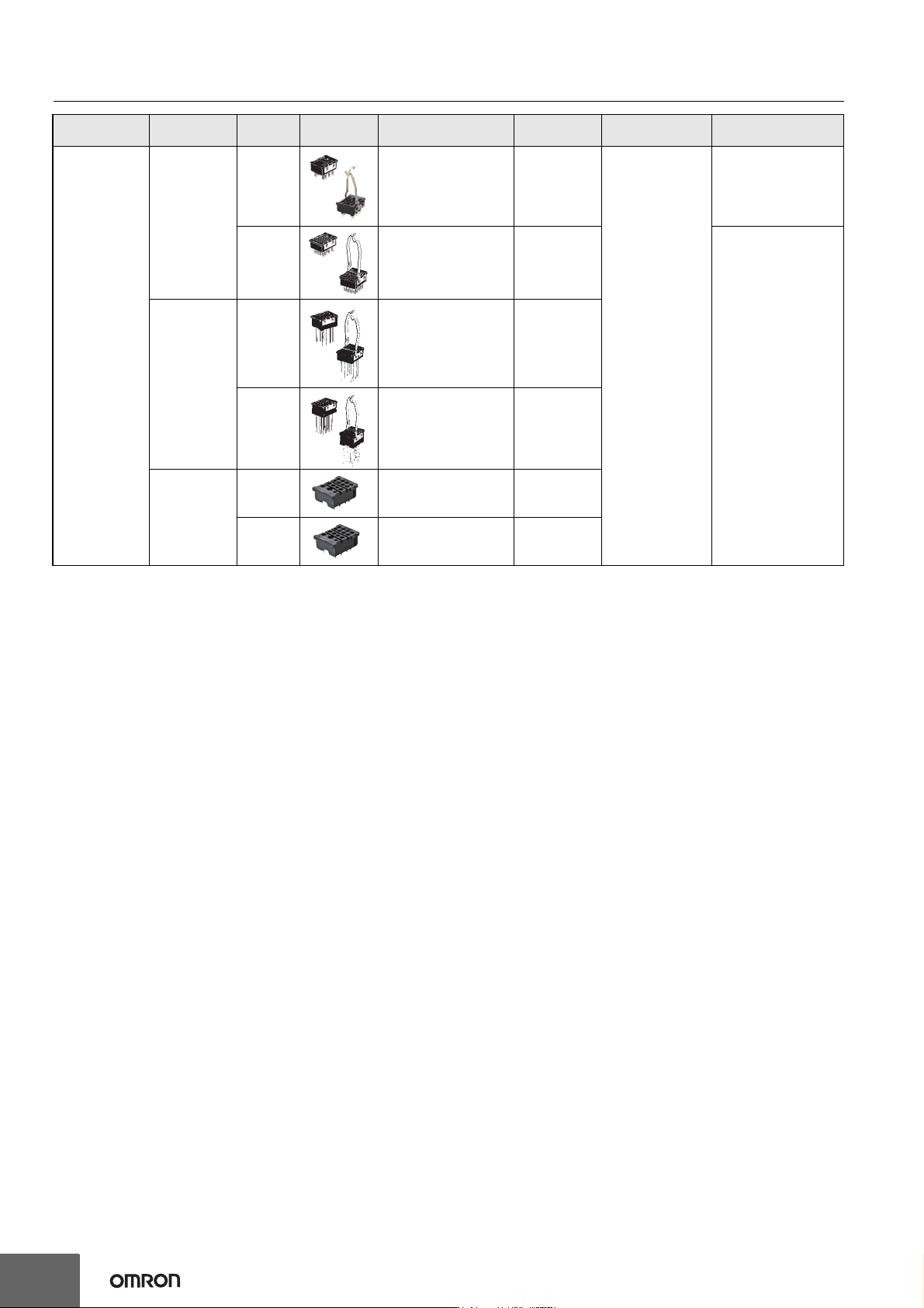
Back-connecting
Solder terminals
2 PY08(-Y1) 7 A
1,500 VAC, 1 min
1000 MΩ min.
4 PY14(-Y1) 3 A
100 MΩ min.
Wrapping
terminals
2 PY08QN(-Y1) 7 A
4 PY14QN(-Y1) 3 A
Relays with
PCB terminals
2 PY08-02 7 A
4 PY14-02 3 A
Mounting
Terminal
type
No. of
poles
Appearance Model Carry current
Dielectric
withstand voltage
Insulation resistance
(see note 2)
MY(S)
25
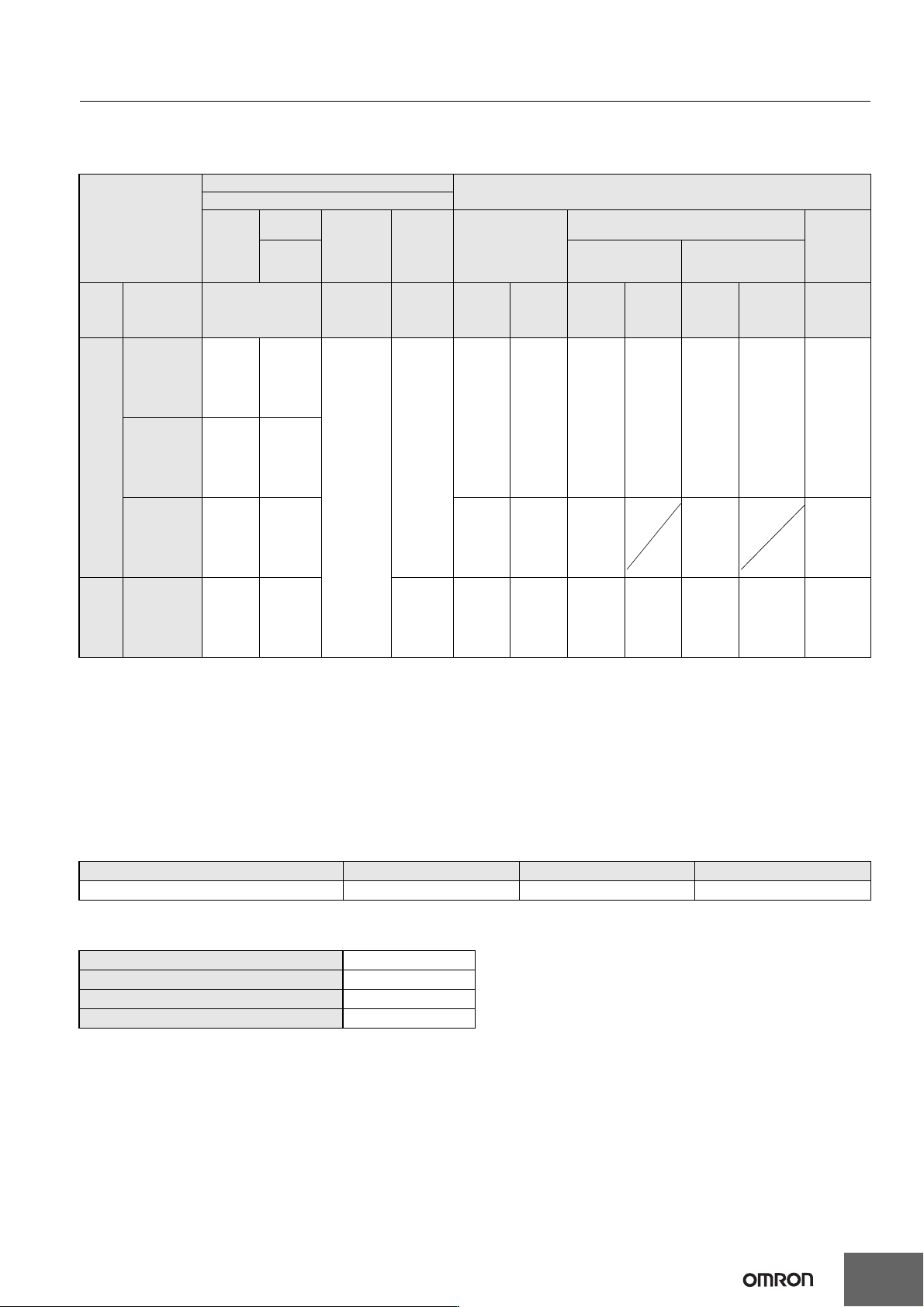
Options (Order Separately)
Connection Socket and Mounting Bracket Selection Table
(The possible combinations of models with plug-in terminals and sockets)
Note: Refer to Common Socket and DIN Track Products for the external dimensions of the Socket Relays and details on Hold-down Clips.
*1. The information in parentheses is the model number of the applicable Mounting Bracket. Mounting Brackets are sold in sets of two. However,
the PYC-P is just one Mounting Bracket.
*2. The PYF@A-E has a terminal cover with finger protection. The Socket and Terminal Cover are integrated into one unit. Round terminals cannot
be used. Use forked terminals or ferrules instead.
*3. A Push-In Plus Terminal Block Socket functions as a release lever to hold or remove a Relay. Refer to PYF-@@-PU/P2RF-@@-PU for details.
*4. If an MYI@(S) Relay with a Latching Lever is used in combination with a PY@-02 Socket for Relays with PCB Terminal Socket and PYC-P
Mounting Brackets, the lever will not operate.
*5. We recommends using the PYC-E1 Mounting Bracket for a MY2I(S) Relay with Latching Lever. (If the PYC-A1 is used with the MY2I(S), the
latching lever will be blocked by the Mounting Bracket and the lever will not operate.)
*6. The Mounting Brackets are applicable for Relays with a height of 36 mm or less. If the Relay height is greater than 53 mm, use Y92H-3 for the
Front-mounting Socket and PYC-1 for the Back-mounting Socket. (The Y92H-3 is a set of two Brackets and the PYC-1 is just one Bracket.)
Mounting Plates for Sockets
Note: PYP-18 and PYP-36 can be cut into any desired length in accordance with the number of Sockets.
DIN-rail and Accessories
Connecting method Front-mounting Sockets (PYF□)
Back-mounting Sockets (PY□)
Mounting method Track or screw mounting
Terminal Type
Screw
terminals
Screw
terminals
Rise-Up
terminals
Push-In
Plus
Terminal
Block
*3
Solder terminals
Wrapping terminals
Relays
with PCB
Terminals
*
4
(finger
protection
structure)
*
2
Terminal length:
25 mm
Terminal length:
20 mm
No. of
poles
Model
(Sold separately:
Hold-down Clips)
*1
Without
Release
Lever
With
Release
Lever
Without
Mounting
Brackets
*
1
With
Mounting
Brackets
Without
Mounting
Brackets
*
1
With
Mounting
Brackets
Without
Mounting
Brackets
*
1
With
Mounting
Brackets
(Sold
separately
: Hold-down
Clips)
*
1
8
MY2(S),
MY2ZN
(except
for MY2K@,
MY2Z@-CR)
PYF08A
(PYC-A1)
PYFZ-08-E
(PYC-A1)
PYF08A-E
(PYC-A1)
PYF08A-N
(PYC-A1)
PYF14-ESN-B
( P Y C - 3 5 - B )
PYF14-ESS-B
(PYC-35-B)
PYF-08-PU
PY08
(PYC-P)
PY08-Y1
PY08QN
(PYC-P)
PY08QN-Y1
PY08QN2
(PYC-P)
PY08QN2-Y1
PY08-02
(PYC-P)
MY2I(S)
*5
PYF08A
(PYC-E1)
PYFZ-08-E
(PYC-A1)
PYF08A-E
(PYC-E1)
PYF08A-N
(PYC-E1)
MY2Z-
@
-CR
*
6
PYF08A
(Y92H-3)
PYFZ-08-E
(PYC-A1)
PFY08A-E
(Y92H-3)
PFY08A-N
(Y92H-3)
PY08
(PYC-1)
PY08-Y3
PY08QN
(PYC-1)
PY08QN2
(PYC-1)
PY08-02
(PYC-1)
14
MY4(S),
MY4I(S),
MY4-CBG,
MY4Q,
MY4(Z)H,
MY2K
PYF14A
(PYC-A1)
PYFZ-14-E
(PYC-A1)
PYF14A-E
(PYC-A1)
PYF14A-N
(PYC-A1)
PYF-14-PU
PY14
(PYC-P)
PY14-Y1
PY14QN
(PYC-P)
PY14QN-Y1
PY14QN2
(PYC-P)
PY14QN2-Y1
PY14-02
(PYC-P)
Socket model For 1 Socket For 18 Sockets For 36 Sockets
PY08, PY08QN(2), PY14, PY14QN(2) PYP-1 PYP-18 PYP-36
Supporting DIN-rail (length = 500 mm) PFP-50N
Supporting DIN-rail (length = 1,000 mm) PFP PFP-100N, PFP-100N2
End Plate PFP-M
Spacer PFP-S