40-575AM.pdf - 第12页
Page 1.5 pick ering test .com Section 1 - T echnical Specification Product Customization Pick ering modules are designed and manufactured on our own flexible manufacturing lines, giving complete product control and enablin…
Page 1.4
pickeringtest.com
Section 1 - Technical Specification
Width and Dimensions
Single slot 3U PXI module (CompactPCI).
Module weight: 410 g.
3D models for these modules in a variety of popular file
formats are available on request.
Switching Specification
Switch Type: Electro-mechanical
Contact Type: Palladium-Ruthenium,
Gold Covered, Bifurcated
Max Switch Voltage: 300 VDC/250 VAC*
Max Power:
Max Switch Current:
Max Continuous Carry Current:
Max Pulsed Carry Current
Example (for single switch path):
62.5 VA, 60 W
2 A
2 A
6 A for 100 ms
(up to 10 % duty cycle)
Max Continuous Total Switch
Path Loading: †
16 W (Example allowed
conditions – 11 channels
at 2 A, please contact
sales office for further
advice)
Initial On Path Resistance:
Off Path Resistance:
Thermal Offset:
<0.35 Ω
>10
9
Ω
10 µV (X to X connection)
Max Number of Simultaneously
Closed Crosspoints:
84 (40-575A)
64 (40-576A)
50 (40-577)
36 (40-578)
28 (40-579)
Operate Time: 6.5 ms
Expected Life (Operations)
Very low power load:
Low power load:
Medium power load:
Full power load:
>1x10
8
>1.5x10
7
(0.1 A 20 VDC)
>5x10
6
(1 A 30 VDC)
>1x10
5
(2 A 30 VDC)
* For full voltage rating, signal sources to be switched must
be fully isolated from mains supply and safety earth.
† Significantly higher total switch path loading is possible
when using Pickering 40-922/923A PXI & 60-102B/103B LXI
chassis’, please contact sales office for details.
RF Specification
Bandwidth
(-3 dB)
typical
40-575A 10 MHz
40-576A 12 MHz
40-577 10 MHz
40-578 15 MHz
40-579 15 MHz
Power Requirements
+3.3 V +5 V +12 V -12 V
40-575A 140 mA 800 mA 0 0
40-576A 150 mA 910 mA 0 0
40-577 140 mA 475 mA 0 0
40-578 140 mA 345 mA 0 0
40-579 140 mA 270 mA 0 0
Note: All power requirement figures are typical values.
10 kHz 100 kHz 1 MHz 10 MHz
Crosstalk
(typical)
40-575A -60 dB -55 dB -35 dB -20 dB
40-576A -60 dB -50 dB -30 dB -15 dB
40-577 -75 dB -60 dB -40 dB -20 dB
40-578 -70 dB -55 dB -35 dB -15 dB
40-579 -70 dB -50 dB -35 dB -15 dB
Isolation
(typical)
40-575A 60 dB 60 dB 40 dB 25 dB
40-576A 65 dB 60 dB 45 dB 30 dB
40-577 85 dB 70 dB 55 dB 40 dB
40-578 70 dB 50 dB 35 dB 20 dB
40-579 70 dB 55 dB 35 dB 20 dB
Connectors
PXI bus via 32-bit P1/J1 backplane connector.
Signals via front panel connectors:
• 40-575A 160-pin male DIN 41612
• 40-576A/577 78-pin male D-type
• 40-578/579 50-pin male D-type
For pin outs please refer to the operating manual.
40-575A/576A/577/578/579
pickeringtest.com
Page 4
Specifications

Page 1.5
pickeringtest.com
Section 1 - Technical Specification
Product Customization
Pickering modules are designed and manufactured on our
own flexible manufacturing lines, giving complete product
control and enabling simple customization to meet very
specific requirements.
Customization can include:
• Alternative relay types
• Mixture of relay types
• Alternative number of relays
• Different performance specifications
All customized products are given a unique part number,
fully documented and may be ordered at any time in the
future. Please contact your local sales office to discuss.
Support Products
eBIRST
Switching System Test Tool
This product is supported by the eBIRST test tools which
simplify the identification of failed relays, the required
eBIRST tools are below. For more information go to:
pickeringtest.com/ebirst
Product Test Tool Adaptor
40-575A
40-576A/577
40-578/579
93-002-001
93-006-001
93-005-001
93-002-410
Not Required
Not Required
Spare Relay Kits
Kits of replacement relays are available for the majority
of Pickering’s PXI switching products, simplifying
servicing and reducing down-time.
Product Relay Kit
40-575A/576A/577/579/579 91-100-001
For further assistance, please contact your local Pickering
sales office.
Mating Connectors & Cabling
For connection accessories for the
40-575A/576A/577/578/579 modules please refer to the
90-001D 160-pin DIN 41612, 90-006D 78-pin D-type and
90-005D 50-pin D-type Connector Accessories data sheet
where a complete list and documentation can be found for
accessories, or refer to the Connection Solutions catalog.
Product Order Codes
Ultra High Density Matrix:
84x4, 1-Pole (2 A, 60 W)
64x6, 1-Pole (2 A, 60 W)
50x8, 1-Pole (2 A, 60 W)
36x12, 1-Pole (2 A, 60 W)
28x16, 1-Pole (2 A, 60 W)
40-575A-001
40-576A-001
40-577-001
40-578-001
40-579-001
PXI & CompactPCI Compliance
The module is compliant with the PXI Specification 2.2.
Local Bus, Trigger Bus & Star Trigger are not implemented.
Uses a 33 MHz 32-bit backplane interface.
Operating/Storage Conditions
Operating Temperature:
Humidity:
Altitude:
0 °C to +55 °C
Up to 90 % non-condensing
5000 m
Storage/Transport Temperature:
Humidity:
Altitude:
-20 °C to +75 °C
Up to 90 % non-condensing
15000 m
Safety & CE Compliance
All modules are fully CE compliant and meet applicable EU
directives:
Low-voltage safety EN61010-1:2010,
EMC Immunity EN61326-1:2013,
Emissions EN55011:2009+A1:2010.
Pickering can supply mating connectors and cable
assemblies to enable easy integration of the
40-575A/576A/577/578/579 matrix modules
40-575A/576A/577/578/579
pickeringtest.com
Page 5
Ordering Information
Page 2.1
pickeringtest.com
Section 2 - Technical Description
Functional Description
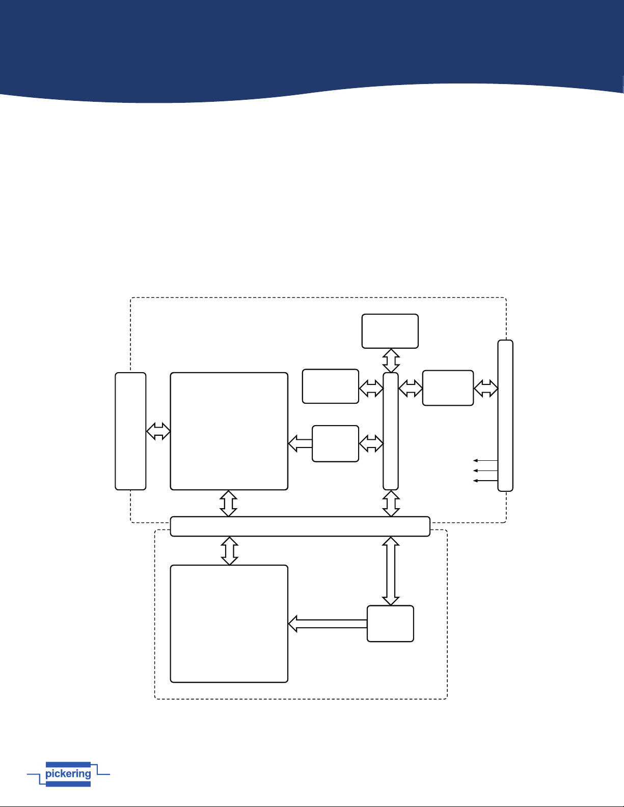
A functional block diagram is provided in Figure 2.1. The Module is powered by the +5V and +3.3V supplies from the PXI
backplane via Compact PCI connector J1. The interface to the user’s equipment is via the front panel mounted 160-pin
DIN41612, 78-pin D-type or 50-pin D-type male connector (dependent upon the module vari.
The module comprises a mother board and a daughter board populated with 1-pole electro-mechanical relays configured as
an 84x4 (40-575A), a 64x6 (40-576A), a 50x8 (40-577), a 36x12 (40-578) or a 28x16 (40-579) matrix. The relays are energised
via control signals from relay drivers U15-22 & U26-33. Each relay driver is loaded with serial data from PCI bridge U1 to
operate the required matrix crosspoint.The main PCI interface circuitry and the drivers and relays that make up one half of
the matrix are built onto the mother board. The daughter board is fitted on top of the mother board and is populated with
the drivers and relays that make up the other half of the matrix. Signals are sent between the two halves of the matrix via
an inter-PCB connector. Module configuration is determined by data stored in EPROM U8. PCI Bridge U1 is configured by
EPROM U7.
Figure 2.1 - PXI Ultra High Density Matrix Module 40-575A: Functional Block Diagram
(the 40-576A, 40-577, 40-578 and 40-579 are functionally the similar but are configured
as 64x6, 50x8, 36x12 and 28x16 matrices respectively)
Electro-mechanical
Relays RL127-252
Matrix
42x4, 1-pole
Electro-mechanical
Relays RL1-126
Matrix
42x4, 1-pole
Front Panel Connector J2
160-pin Male DIN 41612
Interconnection
Daughter Board
Relay
Drivers
U15-22
Relay
Drivers
U26-33
Module
Configuration
U8
PCI Bridge
Configuration
U7
Level
Translators
U2-3
PCI Bridge U1
Compact PCI Bus Connector J1
Mother Board
+5V
+3.3V
GND
40-575A PXI High Density
84x4 Matrix Module