40-575AM.pdf - 第30页
Page 7.3 pick ering test .com Section 7 - Maintenance Information Relays Used in Signal P ath - 40-575A (84x4 Matrix) Y1 Y2 Y3 Y4 Y1 Y2 Y3 Y4 Mother Board X1 2 1 2 1 3 1 3 1 Daughter Board X43 128 127 128 127 129 127 129…
Page 7.2
pickeringtest.com
Section 7 - Maintenance Information
Relay Fault Finding
In the event of a switch failure in the ultra high density matrix module, the following procedure will help locate which
relays need replacing. The module uses through-hole relays that are straight forward to replace providing normal good
practice is followed to avoid PCB damage.
Identify Which Crosspoints Have Failed
First you will need to check which matrix crosspoints have failed by identifying their X and Y coordinates. It should be
noted that a single relay failure can cause more than one crosspoint failure.
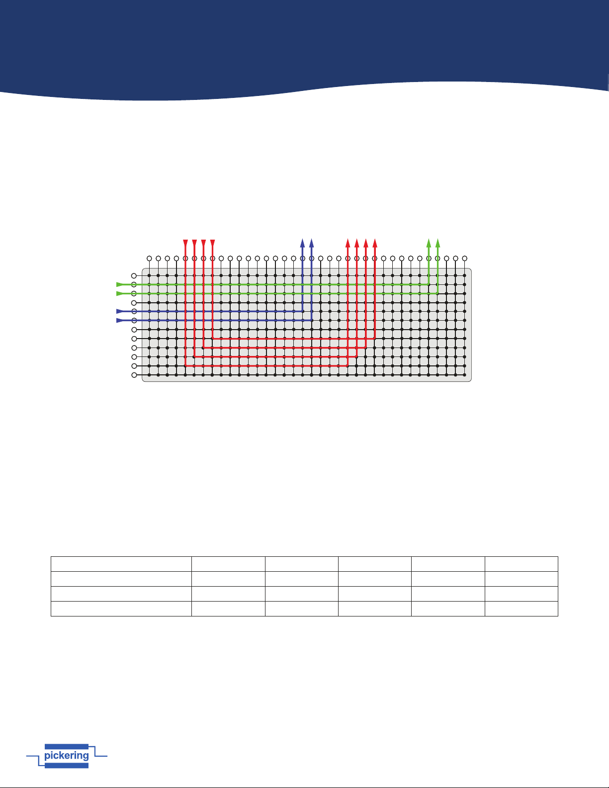
Figure 7.1 - Example use of the High Density Matrix -
Connections can be made from X to Y or X to X using the Y bus as a path
Signals can be routed through the matrix in two ways: Connecting an X port to a Y port using one crosspoint, or connecting
an X port to another X port using two crosspoints and a Y line. If there is a failure on an X to X route it is important to
know which Y line was used in the failed path. Test to see which crosspoint has failed by routing the path to a different X
connection. Make a list of all the failed crosspoints you can find.
Identify The Board With Failed Relays
The modules in this range consist of a mother board and a daughter board, each containing half the total number of relays
that make up the matrix. Mother and daughter boards share the same Y connections. Use the table below to locate which
boards contain the faulty crosspoints. Also, it may help to refer to the architecture diagram in Figures 2.1
Module Number 40-575A 40-576A 40-577 40-578 40-789
Matrix Size 84x4 64x6 50x8 36x12 28x16
Mother Board X Connections X1 to X42 X1 to X32 X1 to X25 X1 to X18 X1 to X14
Daughter Board X Connections X43 to X84 X33 to X64 X26 to X50 X19 to X36 X15 to X28
Locating the Defective Relays
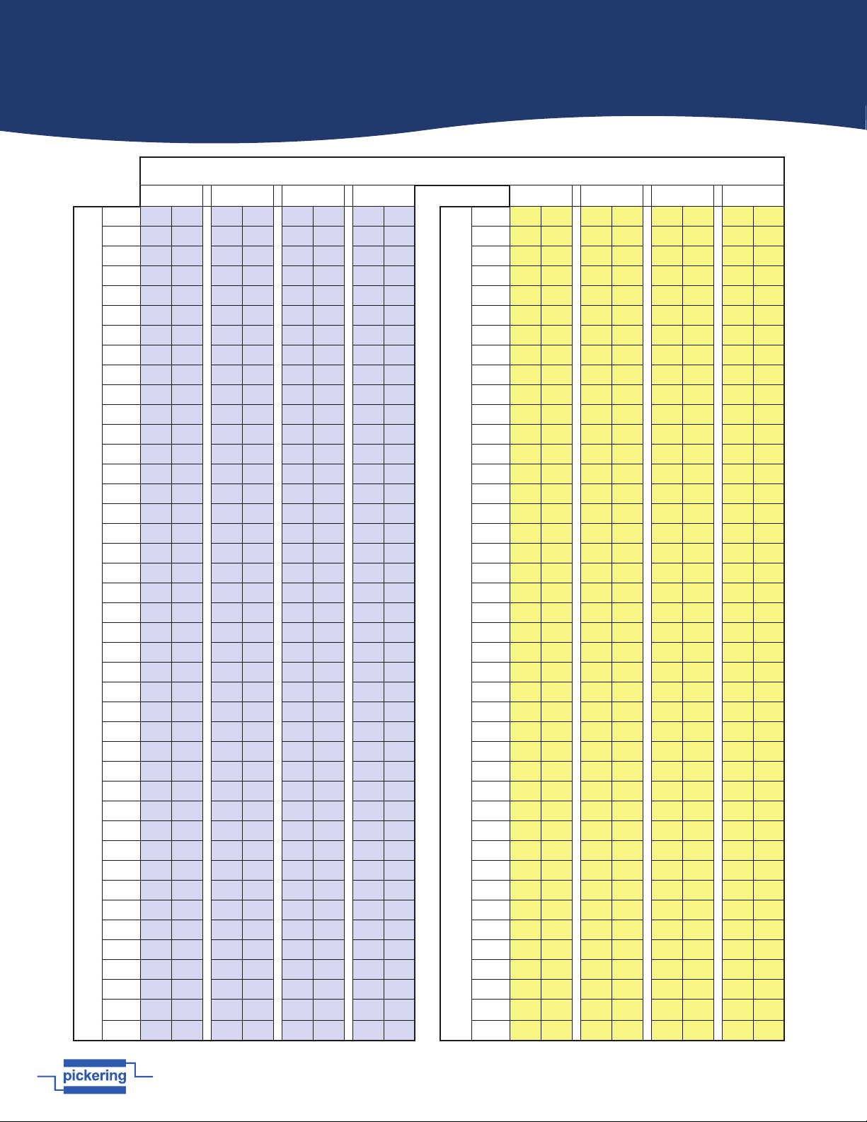
The tables on the following pages provide a cross reference between the matrix crosspoints and the physical relays on the
boards. Using your list of faulty crosspoints, locate the relays on the mother and daughter boards that need to be replaced
and create a defective relay list.
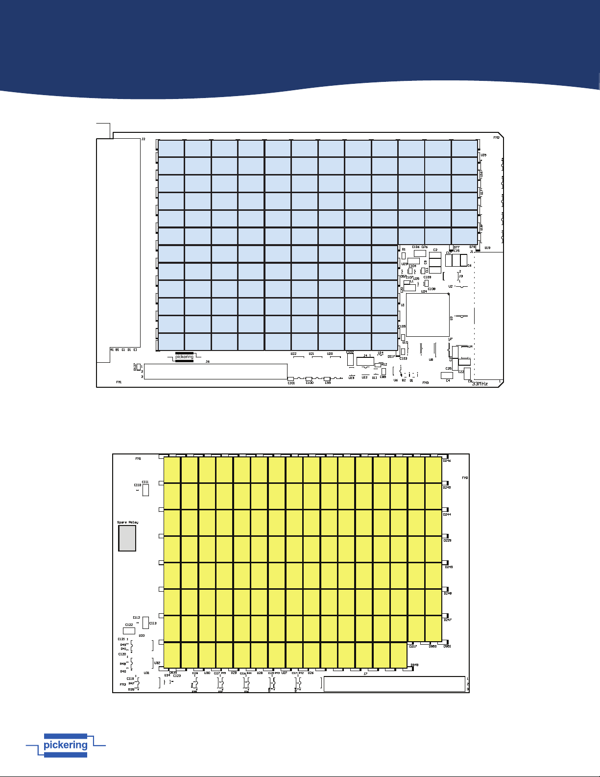
Remove the faulty module from the host chassis and using your defective relay list, refer to the PCB layout diagrams that
follow the relay tables to locate the faulty relays. Replace the relays as required, re-fit the module into the host chassis
then re-test to establish if the repair has been successful.
Page 7.3
pickeringtest.com
Section 7 - Maintenance Information
Relays Used in Signal Path - 40-575A (84x4 Matrix)
Y1 Y2 Y3 Y4 Y1 Y2 Y3 Y4
Mother Board
X1 2 1 2 1 3 1 3 1
Daughter Board
X43 128 127 128 127 129 127 129 127
X2 5 4 5 4 6 4 6 4 X44 131 130 131 130 132 130 132 130
X3 8 7 8 7 9 7 9 7 X45 134 133 134 133 135 133 135 133
X4 11 10 11 10 12 10 12 10 X46 137 136 137 136 138 136 138 136
X5 14 13 14 13 15 13 15 13 X47 140 139 140 139 141 139 141 139
X6 17 16 17 16 18 16 18 16 X48 143 142 143 142 144 142 144 142
X7 20 19 20 19 21 19 21 19 X49 146 145 146 145 147 145 147 145
X8 23 22 23 22 24 22 24 22 X50 149 148 149 148 150 148 150 148
X9 26 25 26 25 27 25 27 25 X51 152 151 152 151 153 151 153 151
X10 29 28 29 28 30 28 30 28 X52 155 154 155 154 156 154 156 154
X11 32 31 32 31 33 31 33 31 X53 158 157 158 157 159 157 159 157
X12 35 34 35 34 36 34 36 34 X54 161 160 161 160 162 160 162 160
X13 38 37 38 37 39 37 39 37 X55 164 163 164 163 165 163 165 163
X14 41 40 41 40 42 40 42 40 X56 167 166 167 166 168 166 168 166
X15 44 43 44 43 45 43 45 43 X57 170 169 170 169 171 169 171 169
X16 47 46 47 46 48 46 48 46 X58 173 172 173 172 174 172 174 172
X17 50 49 50 49 51 49 51 49 X59 176 175 176 175 177 175 177 175
X18 53 52 53 52 54 52 54 52 X60 179 178 179 178 180 178 180 178
X19 56 55 56 55 57 55 57 55 X61 182 181 182 181 183 181 183 181
X20 59 58 59 58 60 58 60 58 X62 185 184 185 184 186 184 186 184
X21 62 61 62 61 63 61 63 61 X63 188 187 188 187 189 187 189 187
X22 65 64 65 64 66 64 66 64 X64 191 190 191 190 192 190 192 190
X23 68 67 68 67 69 67 69 67 X65 194 193 194 193 195 193 195 193
X24 71 70 71 70 72 70 72 70 X66 197 196 197 196 198 196 198 196
X25 74 73 74 73 75 73 75 73 X67 200 199 200 199 201 199 201 199
X26 77 76 77 76 78 76 78 76 X68 203 202 203 202 204 202 204 202
X27 80 79 80 79 81 79 81 79 X69 206 205 206 205 207 205 207 205
X28 83 82 83 82 84 82 84 82 X70 209 208 209 208 210 208 210 208
X29 86 85 86 85 87 85 87 85 X71 212 211 212 211 213 211 213 211
X30 89 88 89 88 90 88 90 88 X72 215 214 215 214 216 214 216 214
X31 92 91 92 91 93 91 93 91 X73 218 217 218 217 219 217 219 217
X32 95 94 95 94 96 94 96 94 X74 221 220 221 220 222 220 222 220
X33 98 97 98 97 99 97 99 97 X75 224 223 224 223 225 223 225 223
X34 101 100 101 100 102 100 102 100 X76 227 226 227 226 228 226 228 226
X35 104 103 104 103 105 103 105 103 X77 230 229 230 229 231 229 231 229
X36 107 106 107 106 108 106 108 106 X78 233 232 233 232 234 232 234 232
X37 110 109 110 109 111 109 111 109 X79 236 235 236 235 237 235 237 235
X38 113 112 113 112 114 112 114 112 X80 239 238 239 238 240 238 240 238
X39 116 115 116 115 117 115 117 115 x81 242 241 242 241 243 241 243 241
X40 119 118 119 118 120 118 120 118 x82 245 244 245 244 246 244 246 244
X41 122 121 122 121 123 121 123 121 x83 248 247 248 247 249 247 249 247
X42
125 124 125 124 126 124 126 124
x84
251 250 251 250 252 250 252 250
Page 7.4
pickeringtest.com
Section 7 - Maintenance Information
RL27 RL26 RL25 RL10 RL12RL11 RL7 RL8 RL9 RL1 RL3RL2
RL15 RL14 RL13 RL22 RL24RL23 RL4 RL5 RL6 RL16 RL18RL17
RL60 RL59 RL58 RL37 RL39RL38 RL19 RL20 RL21 RL31 RL33RL32
RL105 RL104 RL103 RL88 RL90RL89 RL34 RL35 RL36 RL46 RL48RL47
RL108 RL107 RL106 RL73 RL75RL74 RL49 RL50 RL51 RL61 RL63RL62
RL120 RL119 RL118 RL43 RL45RL44 RL52 RL53 RL54 RL76 RL78RL77
RL93 RL92 RL91 RL28 RL30RL29 RL40 RL41 RL42
RL114 RL113 RL112 RL64 RL66RL65 RL55 RL56 RL57
RL96 RL95 RL94 RL79 RL81RL80 RL70 RL71 RL72
RL111 RL110 RL109 RL67 RL69RL68 RL85 RL86 RL87
RL126 RL125 RL124 RL82 RL84RL83 RL100 RL101 RL102
RL123 RL122 RL121 RL97 RL99RL98 RL115 RL116 RL117
RL133 RL134 RL135 RL130 RL131 RL132 RL160 RL161
RL148 RL149 RL150 RL145 RL146 RL147 RL176 RL162
RL163 RL164 RL165 RL238 RL239 RL240 RL175 RL177
RL178 RL179 RL180 RL139 RL140 RL141 RL190 RL191
RL223 RL224 RL225 RL154 RL155 RL156 RL206 RL192
RL208 RL209 RL210 RL214 RL215 RL216 RL205 RL207
RL193 RL194 RL195 RL199 RL200 RL201 RL127 RL128
RL166 RL167 RL168 RL184 RL185 RL186 RL143 RL129
RL151 RL152 RL153 RL169 RL170 RL171 RL142 RL144
RL136 RL137 RL138 RL241 RL242 RL243 RL157 RL158
RL250 RL251 RL252 RL226 RL227 RL228 RL173 RL159
RL235 RL236 RL237 RL211 RL212 RL213 RL172 RL174
RL220 RL221 RL222 RL196 RL197 RL198 RL187 RL188
RL217 RL218 RL219 RL181 RL182 RL183 RL203 RL189
RL232 RL233 RL234 RL230 RL231 RL202 RL204
RL247 RL248 RL249 RL229 RL244 RL245 RL246
Spare
Figure 7.2 - 40-575A Matrix Module: Motherboard Relay Locations
Figure 7.3 - 40-575A Matrix Module: Daughterboard Relay Locations