40-575AM.pdf - 第21页
Page 4.5 pick ering test .com Section 4 - Programming Using Pickering Driv ers In Lab VIEW Example Use of Pickering Driv ers in Lab VIEW T o download Lab VIEW examples, please go t o: Using Pickering Drivers in Lab VIEW …

Page 4.4
pickeringtest.com
Section 4 - Programming
Programming the Matrix Using The IVI Driver, Direct I/O Driver or VISA Driver
This section provides some code fragments which show how to control the High Density Matrix using the IVI Driver, Direct
I/O Driver or the VISA Driver.
Once the drivers are installed the manual “Sys40Prg.pdf” and driver help files which fully describes these functions can
be found in the Pickering folder(s) or the Pickering entries on your Start Menu.
The card must be opened before use and closed after using the following function calls:
Direct Driver - Open with PIL_OpenCards or PIL_OpenSpeciedCard and close with PIL_CloseCards or
PIL_CloseSpeciedCards respectively.
VISA Driver - Open with pipx40_init, and close with, pipx40_close.
Setting a Matrix Crosspoint:
Using the IVI driver:
pi40iv_Connect(vi, “x1”, “y2”); //set crosspoint x1, y2 to on
pi40iv_Disconnect(vi, “x1”, “y2”); //set crosspoint x1, y2 to o
Using the Pickering Direct I/O driver:
DWORD SubUnit = 1;
PIL_ClearSub(CardNo, SubUnit); //clear all crosspoints to o state
PIL_OpCrosspoint(CardNo, SubUnit, 2, 1, 1); //set crosspoint x1, y2 to on
PIL_OpCrosspoint(CardNo, SubUnit, 2, 1, 0); //set crosspoint x1, y2 to o
Using the VISA driver:
ViUInt32 SubUnit = 1;
pipx40_clearSub(vi, SubUnit); //clear all crosspoints o state
pipx40_setCrosspointState (vi, SubUnit, 2, 1, VI_ON); //set crosspoint x1, y2 on
pipx40_setCrosspointState (vi, SubUnit, 2, 1, VI_OFF); //set crosspoint x1, y2 o
Page 4.5
pickeringtest.com
Section 4 - Programming
Using Pickering Drivers In LabVIEW
Example Use of Pickering Drivers in LabVIEW
To download LabVIEW examples, please go to:
Using Pickering Drivers in LabVIEW
Most Pickering drivers include a LabVIEW wrapper to permit full operation of the Pickering product from the LabVIEW
environment. These wrappers are normally installed to the current LabVIEW folder system during installation of the
Pickering driver.
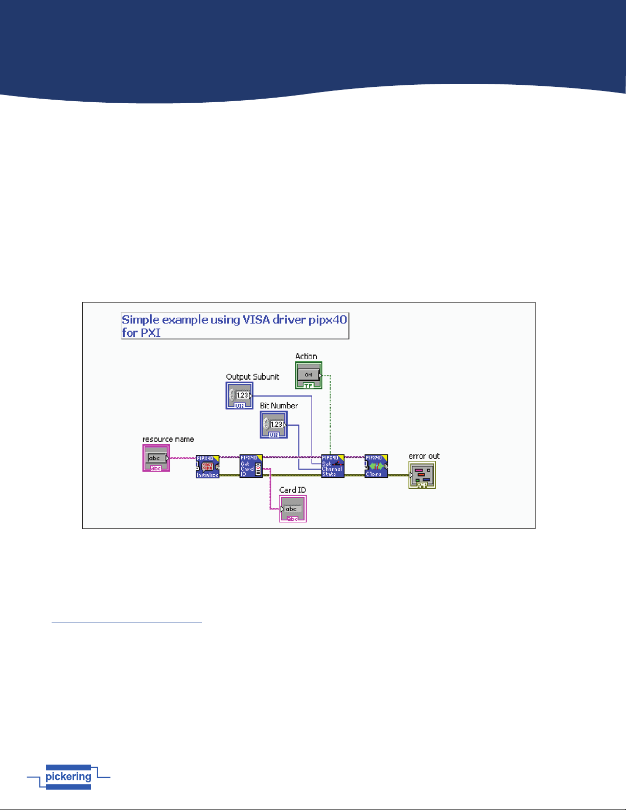
The process of controlling a Pickering product normally consists of the following steps:
1. Open a control session on the product.
2. Use functions in the library to operate the product.
3. Close the control session.
Following is a simple example of the use of the most common Pickering drivers:
Page 5.1
pickeringtest.com
Section 5 - Connectors
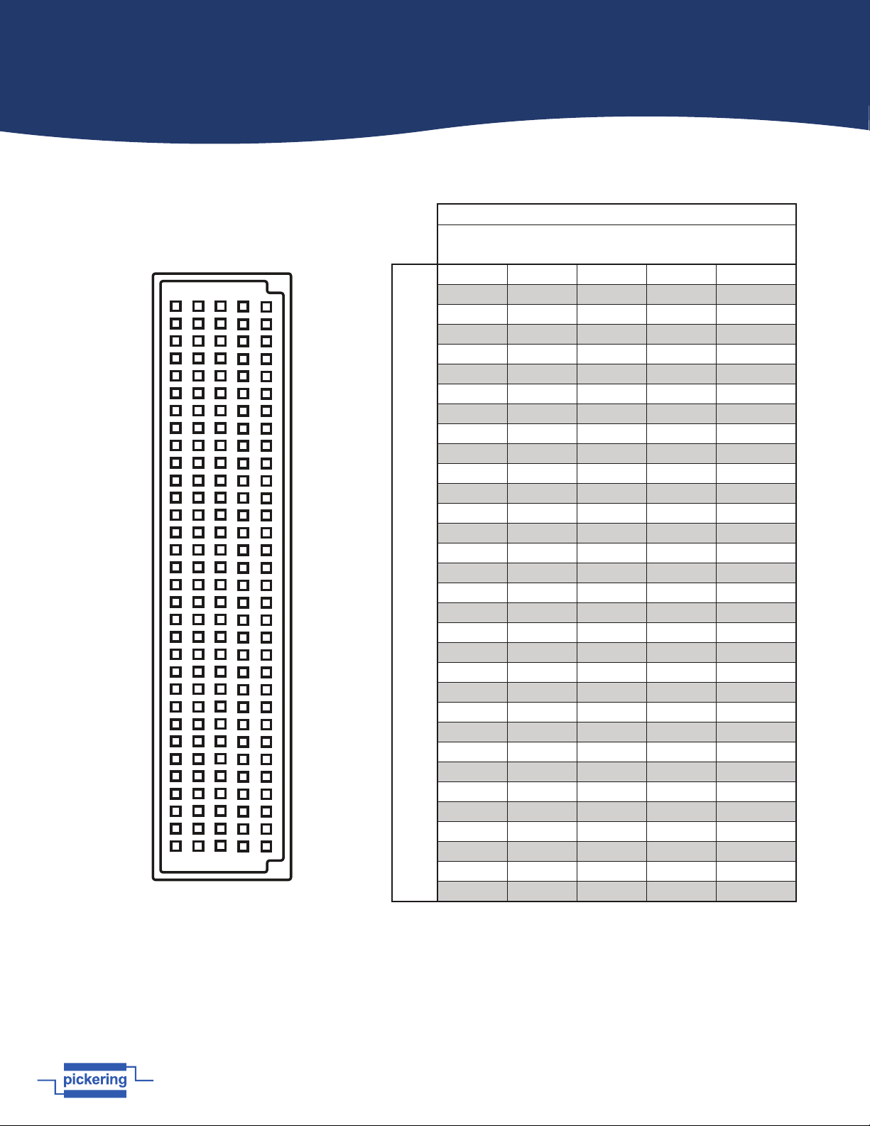
Figure 5.1 - 2 A 1-Pole 84x4 Matrix Module 40-575A-001 Pinout
(160-pin DIN41612 male connector pinout viewed from front of module)
160-pin Male DIN 41612 Connector
A B C D E
32
31
30
29
28
27
26
25
24
23
22
21
20
19
18
17
16
15
14
13
12
11
10
9
8
7
6
5
4
3
2
1
40-575A-001 - Pinout
Connector Columns
A B C D E
Connector Rows
32 X1 X2 X3 X4 X5
31 X6 X7 X8 X9 X10
30 X11 X12 X13 X14 X15
29 X16 X17 X18 X19 X20
28 X21 X22 X23 X24 X25
27 X26 X27 X28 X29 X30
26 X31 X32 X33 X34 X35
25 X36 X37 X38 X39 X40
24 X41 X42 X43 X44 X45
23 X46 X47 X48 X49 X50
22 X51 X52 X53 X54 X55
21 X56 X57 X58 X59 X60
20 X61 X62 X63 X64 X65
19 X66 X67 X68 X69 X70
18 X71 X72 X73 X74 X75
17 X76 X77 X78 X79 X80
16 X81 X82 X83 X84 –
15 – – – – –
14 – – – – –
13 – – – – –
12 – – – – –
11 – – – – –
10 – – – – –
9 – – – – –
8 – – – – –
7 – – – – –
6 – – – – –
5 – – – – –
4 – – – – –
3 – – – – –
2 – Y! Y2 Y3 Y4
1 FP_GND – – – –