40-575AM.pdf - 第28页
Page 7.1 pick ering test .com Section 7 - Maintenance Information General Cleaning • Isolate the electrical power from the chassis and ensure that no user I/O signals are being applied. • Wipe the product & chassis s…
Page 6.1
pickeringtest.com
Section 6 - Troubleshooting
Installation Problems
The Plug & Play functionality of Pickering switch cards generally ensures trouble-free installation.
If you do experience any installation problems you should first ensure that all cards are properly seated in their slots.
Improperly mated cards may go undetected by the operating system, or may be detected as a card of an unknown type.
They can also cause the computer to freeze at various stages in the boot sequence.
If your system employs a remote control interface you should check the integrity of all remote control interface links.
When the system is powered up, and during Windows start-up, you should expect to see periodic activity on the remote
control interface RX/TX (yellow) indicators, clearing to leave only the PWR/LNK (green) LEDs illuminated. The RX/TX
indicators should show activity when you attempt to access a card.
Diagnostic Utility
The Pickering Diagnostic Utility (accessible through the Programs>>Pickering>>PXI Utilities menu) generates a
diagnostic report of the system’s PCI configuration, highlighting any potential configuration problems. Specific details of
all installed Pickering switch cards are included. All the installed Pickering switch cards should be listed in the “Pilpxi
information” section - if one or more cards is missing it may be possible to determine the reason by referring to the PCI
configuration dump contained in the report, but interpretation of this information is far from straightforward, and the
best course is to contact Pickering support: support@pickeringtest.com, if possible including a copy of the diagnostic
report.
In the “VISA information” section, if VISA is not installed its absence will be reported. This does not affect operation using
the Direct I/O driver, and is not a problem unless you wish to use VISA. VISA is a component of National Instruments
LabWindows/CVI and LabVIEW, or is available as a standalone environment.
If VISA is present and is of a sufficiently recent version, the section “Pipx40 information” should present a listing similar
to “Pilpxi information”.
Please note that the Diagnostic Utility cannot access cards if they are currently opened by some other application, such
as the Test Panels or Terminal Monitor.
Refer to the Warnings and Cautions at the front of this manual.
!
Page 7.1
pickeringtest.com
Section 7 - Maintenance Information
General Cleaning
• Isolate the electrical power from the chassis and ensure that no user I/O signals are being applied.
• Wipe the product & chassis surfaces with a clean dry anti-static cloth only.
Software Update
For PXI modules operating in a PXI chassis, no module software updates are required. For the latest version of the
driver please refer to our web site pickeringtest.com where links to our Software Download page will provide the
latest version of the driver software for the various programming environments encountered.
For PXI modules which are supported in one of Pickering Interfaces’ Modular LXI Chassis (such as the 60-102D
and 60-103D) no module software update is required. If the module was introduced after the LXI chassis was
manufactured the module may not be recognized, in this case the chassis firmware may need upgrading. This is a
simple process which is described in the manual for the Modular LXI Chassis.
Periodic Maintenance
This product and its corresponding chassis do not require any periodic maintenance.
!
Refer to the Warnings and Cautions at the front of this manual.
Switching System Test Tools
We recommend the use of eBIRST to provide a check of the correct operation of relays and to identify the location of
any faulty relay. For more information vist: pickeringtest.com/ebirst
Page 7.2
pickeringtest.com
Section 7 - Maintenance Information
Relay Fault Finding
In the event of a switch failure in the ultra high density matrix module, the following procedure will help locate which
relays need replacing. The module uses through-hole relays that are straight forward to replace providing normal good
practice is followed to avoid PCB damage.
Identify Which Crosspoints Have Failed
First you will need to check which matrix crosspoints have failed by identifying their X and Y coordinates. It should be
noted that a single relay failure can cause more than one crosspoint failure.
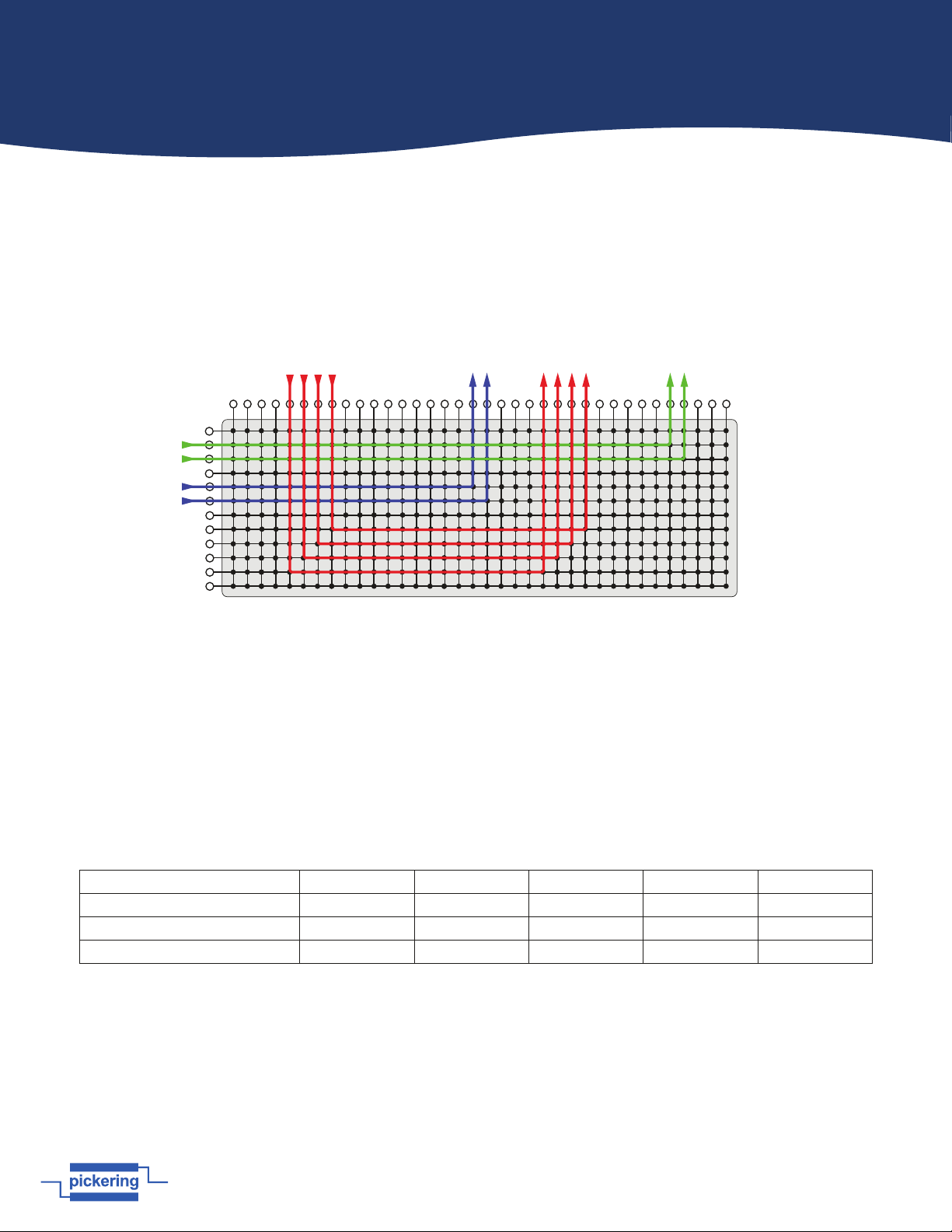
Figure 7.1 - Example use of the High Density Matrix -
Connections can be made from X to Y or X to X using the Y bus as a path
Signals can be routed through the matrix in two ways: Connecting an X port to a Y port using one crosspoint, or connecting
an X port to another X port using two crosspoints and a Y line. If there is a failure on an X to X route it is important to
know which Y line was used in the failed path. Test to see which crosspoint has failed by routing the path to a different X
connection. Make a list of all the failed crosspoints you can find.
Identify The Board With Failed Relays
The modules in this range consist of a mother board and a daughter board, each containing half the total number of relays
that make up the matrix. Mother and daughter boards share the same Y connections. Use the table below to locate which
boards contain the faulty crosspoints. Also, it may help to refer to the architecture diagram in Figures 2.1
Module Number 40-575A 40-576A 40-577 40-578 40-789
Matrix Size 84x4 64x6 50x8 36x12 28x16
Mother Board X Connections X1 to X42 X1 to X32 X1 to X25 X1 to X18 X1 to X14
Daughter Board X Connections X43 to X84 X33 to X64 X26 to X50 X19 to X36 X15 to X28
Locating the Defective Relays
The tables on the following pages provide a cross reference between the matrix crosspoints and the physical relays on the
boards. Using your list of faulty crosspoints, locate the relays on the mother and daughter boards that need to be replaced
and create a defective relay list.
Remove the faulty module from the host chassis and using your defective relay list, refer to the PCB layout diagrams that
follow the relay tables to locate the faulty relays. Replace the relays as required, re-fit the module into the host chassis
then re-test to establish if the repair has been successful.