40-575AM.pdf - 第16页
Page 3.3 pick ering test .com Section 3 - Installation Figure 3.3 - General Soft Front P anel Selector T esting Operation After installation of the hardware and Pickering P XI Driver software package start the General So…
Page 3.2
pickeringtest.com
Section 3 - Installation
Software Installation
First install the appropriate Pickering PXI switch card drivers by running the installer program Setup.exe (provided in a compressed zip
file), either from the CD-ROM supplied, or by downloading the latest version from our website: pickeringtest.com - the recommended
method. Setup is accompanied by a ReadMe file containing additional installation information. A single installation covers all Pickering
switching and simulation PCI, PXI and PXIe products.
When installation completes, the installed drivers’ ReadMe file is offered for display. It can also be displayed later using a shortcut on
the Programs>>Pickering menu.
If you are not a LabVIEW user you should choose the “full” version, and once that has been installed run the LabVIEW Runtime Engine
installer via the shortcut on the Programs>>Pickering menu. In the absence of LabVIEW the Runtime Engine is required to support the
Pickering Test Panels application.
!
Hardware Installation Electrical Connection (Chassis)
The chassis must be electrically installed in accordance with local regional electrical codes by a qualified engineer.
The chassis must be grounded.
Electrostatic discharge can damage the components on the module. To avoid such damage in handling the board refer to page vi.
Ensure that there is adequate ventilation.
The module should be installed in accordance with the following procedure:
1. Ensure that the system is turned OFF but still connected to mains so that it remains grounded.
2. Choose an appropriate slot in the rack.
3. Remove the blanking plate for the chosen slot.
4. Ensure that the injector/ejector handle is in its downward position. Align the module with the card guides on the top and bottom of
the slot.
Do not raise the injector/ejector handle whilst inserting the module as the module will not insert properly.
5. Hold the handle whilst slowly sliding the module into the card guides until the handle catches on the injector/ejector rail (refer to
Figure 3.1).
6. Raise the injector/ejector handle until the module firmly seats into the backplane. The front panel of the module should be flush with
the front panel of the chassis.
7. Secure the front panel of the module using both screws to the chassis front panel mounting rails.
8. In a system employing a remote control interface to connect an external controller to a PXI chassis or to link multiple chassis,
power-up the system as follows:
a. For a system comprising an external controller and one chassis, power up the chassis before powering up the external controller.
b. For a system comprising more than one chassis, turn ON the last chassis in the system followed by the penultimate, etc, and
finally turn ON the external controller or chassis containing the system controller.
9. For Pickering Interfaces modular LXI installation there is no requirement to use any particular power up sequence.
Page 3.3
pickeringtest.com
Section 3 - Installation
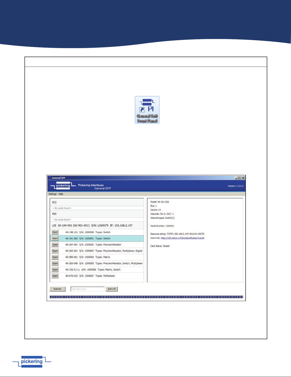
Figure 3.3 - General Soft Front Panel Selector
Testing Operation
After installation of the hardware and Pickering PXI Driver software package start the General Soft Front Panel (GSFP) using the
desktop icon or via the Start menu (Start Menu-> Pickering Interfaces Ltd -> General Soft Front Panel).
A selector panel will appear, listing all installed Pickering PCI, PXI/PXIe or LXI switch cards and resistor cards. Click on the card you
wish to control, and a graphical control panel is presented allowing operation of the card. Panels can be opened simultaneously for
all the installed cards.
More details how to use the GSFP can be found in the manual, via menu Help\Manual.
Figure 3.2 - General Soft Front Panel Icon

Page 4.1
pickeringtest.com
Section 4 - Programming
Programming options for Pickering Interfaces PXI Modules
For information on the installation and use of drivers and the programming of Pickering’s products in various software
environments, please refer to the Software User Manual.
This is available as a download from:
pickeringtest.com/support/software-drivers-and-downloads
Also, it can be accessed from the DVD supplied with the product:
<DVD_DRIVE>\downloads\Documentation\Software-Manual.pdf
Relay Cycle Counting Feature Details
For information related to the relay cycle counting feature present on the 40-575A-001 and 40-576A-001 versions of this
product, please refer to the Relay Cycle Counting User Guide.
This is available as a download from:
pickeringtest.com/portal/web/256/content/private/manuals/Relay-Cycle-Counting-User-Guide.pdf
Also, it can be accessed from the DVD supplied with the product:
<DVD_DRIVE>\downloads\Documentation\Relay-Cycle-Counting-User-Guide.pdf