40-575AM.pdf - 第18页
Page 4.2 pick ering test .com Section 4 - Programming Matrix Architecture The 40-575A is a single pole switching matrix with 84 connections on the X -axis and 4 connections on the Y-axis. Connections are made by operatin…

Page 4.1
pickeringtest.com
Section 4 - Programming
Programming options for Pickering Interfaces PXI Modules
For information on the installation and use of drivers and the programming of Pickering’s products in various software
environments, please refer to the Software User Manual.
This is available as a download from:
pickeringtest.com/support/software-drivers-and-downloads
Also, it can be accessed from the DVD supplied with the product:
<DVD_DRIVE>\downloads\Documentation\Software-Manual.pdf
Relay Cycle Counting Feature Details
For information related to the relay cycle counting feature present on the 40-575A-001 and 40-576A-001 versions of this
product, please refer to the Relay Cycle Counting User Guide.
This is available as a download from:
pickeringtest.com/portal/web/256/content/private/manuals/Relay-Cycle-Counting-User-Guide.pdf
Also, it can be accessed from the DVD supplied with the product:
<DVD_DRIVE>\downloads\Documentation\Relay-Cycle-Counting-User-Guide.pdf
Page 4.2
pickeringtest.com
Section 4 - Programming
Matrix Architecture
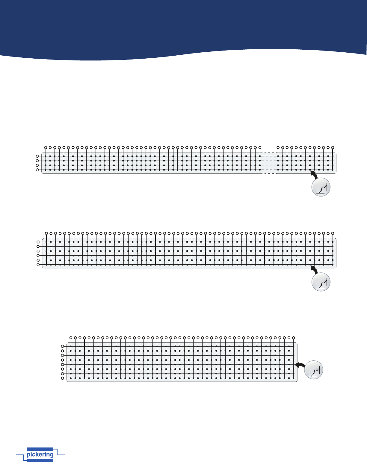
The 40-575A is a single pole switching matrix with 84 connections on the X-axis and 4 connections on the Y-axis.
Connections are made by operating the relays at the crosspoints between X and Y lines allowing single X-Y connections,
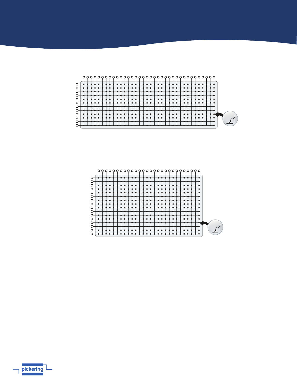
or X-X connections using a Y line as a path. The 40-576A, 40-577, 40-578 and 40-579 are controlled in the same way but
have matrix sizes of 64x6, 50x8, 36x12 and 28x16 respectively. The matrix architectures are shown in the diagrams below:
40-575A-001 84x4 Matrix
X2
X4
X8
X1
X3
X5
X6
X7
Y1
Y2
X12
X9
X10
X11
X14
X16
X13
X15
X17
X18
X19
X24
X22
X23
X21
X20
X25
X26
X27
X32
X30
X31
X29
X28
X34
X36
X40
X33
X35
X37
X38
X39
X44
X41
X42
X43
X46
X48
X45
X47
X76
X74
X75
X73
X72
X77
X78
X79
X84
X82
X83
X81
X80
Matrix
Crosspoint
Y3
Y4
40-576A-001 64x6 Matrix
X2
X4
X8
X1
X3
X5
X6
X7
Y1
Y2
X12
X9
X10
X11
X14
X16
X13
X15
X17
X18
X19
X24
X22
X23
X21
X20
X25
X26
X27
X32
X30
X31
X29
X28
X34
X36
X40
X33
X35
X37
X38
X39
X44
X41
X42
X43
X46
X48
X45
X47
X56
X54
X55
X53
X52
X57
X58
X59
X64
X62
X63
X61
X60
Y3
Y4
X51
X49
X50
Y5
Y6
Matrix
Crosspoint
40-577-001 50x8 Matrix
X2
X4
X8
X1
X3
X5
X6
X7
Y1
Y2
X12
X9
X10
X11
X14
X16
X13
X15
X17
X18
X19
X24
X22
X23
X21
X20
X25
X26
X27
X32
X30
X31
X29
X28
X34
X36
X40
X33
X35
X37
X38
X39
X44
X41
X42
X43
X46
X48
X45
X47
Y3
Y4
X49
X50
Y5
Y6
Y7
Y8
Matrix
Crosspoint
Page 4.3
pickeringtest.com
Section 4 - Programming
NOTE: The matrix supports concurrent switch paths for X to X and Y to X connections, however connections between
different Y axis lines (e.g. Y1 to Y2) are not permitted.
The entire matrix is treated as a single programming sub-unit designated as Sub-Unit 1. Some simple examples are show
on the next page using the provided drivers: the IVI driver, the Direct IO driver, and the IVI compliant driver.
40-578-001 36x12 Matrix
X2
X4
X8
X1
X3
X5
X6
X7
Y1
Y2
X12
X9
X10
X11
X14
X16
X13
X15
X17
X18
X19
X24
X22
X23
X21
X20
X25
X26
X27
X32
X30
X31
X29
X28
X34
X36
X33
X35
Y3
Y4
Y5
Y6
Matrix
Crosspoint
Y7
Y8
Y9
Y10
Y11
Y12
40-579-001 28x16 Matrix
X2
X4
X8
X1
X3
X5
X6
X7
Y1
Y2
X12
X9
X10
X11
X14
X16
X13
X15
X17
X18
X19
X24
X22
X23
X21
X20
X25
X26
X27
X28
Y3
Y4
Y5
Y6
Matrix
Crosspoint
Y7
Y8
Y9
Y10
Y11
Y12
Y13
Y14
Y15
Y16