40-575AM.pdf - 第6页
Page (vi) Warnings & C autions WARNING - Hazardous En vironments S ymbol This product is not specifically designed f or use in hazardous environments, for e xample in e xplosive atmospheres. If the product is to be us…

Page (v)
Contents
Copyright Statement ........................................................................................................................................................(ii)
Technical Support and Warranty ...................................................................................................................................(iii)
Product Safety...................................................................................................................................................................(iv)
Contents (this page).........................................................................................................................................................(v)
Warnings and Cautions ...................................................................................................................................................(vi)
Section 1
Technical Specification ....................................................................................................................................................1.1
Section 2
Technical Description ......................................................................................................................................................2.1
Functional Description ...............................................................................................................................................2.1
Section 3
Installation .........................................................................................................................................................................3.1
Pre Operation Checks ................................................................................................................................................3.1
Hardware Installation ................................................................................................................................................3.2
Software Installation ..................................................................................................................................................3.2
Testing Operation ........................................................................................................................................................3.3
Section 4
Programming Guide .........................................................................................................................................................4.1
Programming Options for Pickering PXI Modules ................................................................................................4.1
Relay Cycle Counting Feature Details .....................................................................................................................4.1
Module Architecture ...................................................................................................................................................4.2
Programming the Module .........................................................................................................................................4.4
Using Pickering Drivers in LabVIEW .......................................................................................................................4.5
Section 5
Connector Information .....................................................................................................................................................5.1
Section 6
Trouble Shooting ..............................................................................................................................................................6.1
Section 7
Maintenance Information ................................................................................................................................................7.1
Appendix A
Product Lifecycle Status - 40-575A ...............................................................................................................................A.1
Product Lifecycle Status - 40-576A ...............................................................................................................................A.2
Page (vi)
Warnings & Cautions
WARNING - Hazardous Environments Symbol
This product is not specifically designed for use in hazardous environments, for example in explosive
atmospheres. If the product is to be used in hazardous environments we recommend that the user ensures
suitable protective measures are taken.
!
CAUTION - Handling of Electrostatic-Sensitive Devices Symbol
Certain semiconductor devices used in this equipment are liable to damage due to static voltage. Observe the
following precautions when handling these devices in their unterminated state, or sub-assemblies containing
these devices:
• Persons removing sub-assemblies from equipment using these devices must be earthed by a wrist strap
and a resistor at the point provided on the equipment.
• Soldering irons used during the repair operations must be low voltage types with earthed tips and isolated
from the mains voltage by a double insulated transformer.
• Outer clothing worn must be unable to generate static charges.
• Printed Circuit Boards (PCBs) fitted with these devices must be stored and transported in anti-static bags.
WARNING - Danger of Electric Shock Symbol
This module may contain hazardous voltages. Before removing the module from the rack remove all supplies
and disconnect user I/O signals.
Unused slots in the PXI/PXIe/LXI chassis are populated with blanking plates to prevent access to user I/O
signals that may be present. Blanking panels are available to order from Pickering in a variety of slot widths.
If the product is not used in this manner for example by using an extender card then additional care must be
taken to avoid contact with exposed signals.
Not to be used in safety critical circuits, refer to the Pickering Interfaces’ terms & conditions of sale.
This module must not be used for the switching of Mains Circuits. For the switching of voltages up to the
module’s full specification, Secondary Circuit power supplies and the Device Under Test must be fully isolated
from the Mains Circuit and the safety earth.
The host chassis must be correctly installed and be connected to mains or factory safety ground, please refer
to your chassis installation manual.
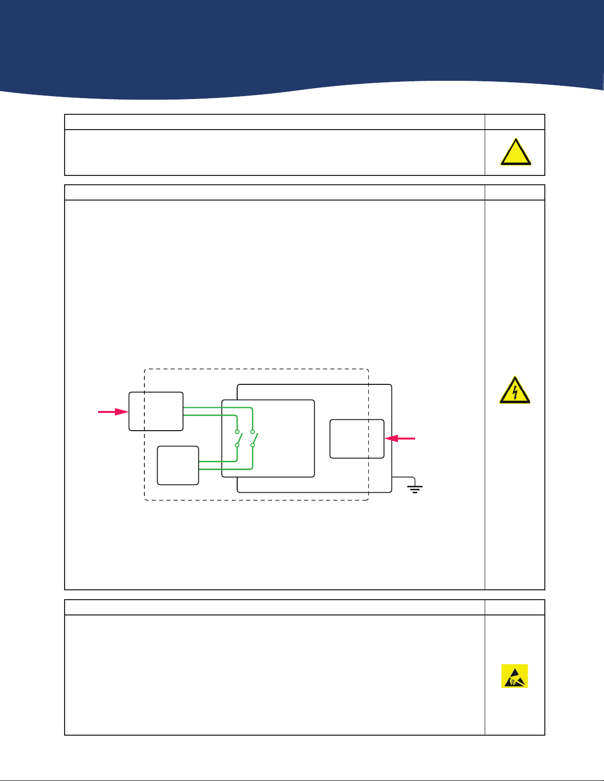
Diagram Showing Separation Between The Mains Circuit and Secondary Circuit / DUT
For the purposes of this document, a Mains Circuit is an installation classified as Overvoltage Category II up to
300V. Separation between the Secondary Circuit and Mains Circuit is achieved by a transformer in which the
primary windings are separated from the secondary windings by reinforced insulation, double insulation, or a
screen connected to the protective conductor terminal.
Switching
Module
Device
Under Test
Power
Supply
Power
Supply
Host Chassis
Secondary Circuit
Mains
Circuit
Mains
Circuit
Mains/Factory
Safety Ground
Page (vii)
CAUTION - Product Documentation Symbol
Suitably qualified & trained users should ensure that the accompanying documentation is fully read
and understood before attempting to install or operate the product.
!
Safety Instructions
Safety Instructions
All cleaning and servicing requires the equipment to be isolated and disconnected from the power source and user I/O
signals (refer to the Maintenance Section).
• Appropriate manual handling procedures should be followed as dictated by the weight of the individual module or the
combined weight of the modules & chassis.
• Should a fault occur with the module or chassis, immediately isolate and disconnect the incoming power to the chassis
and the user I/O signals.
• Ensure the equipment is installed, operated and maintained by trained and authorised personnel.
• For suitably equipped products in the event of an emergency press the red “emergency stop” button situated on the
front of the unit.