40-575AM.pdf - 第7页
Page (vii) CAUTION - Product Documentation Symbol Suitably qualified & trained users should ensur e that the accompanying documentation is fully read and understood before attempting t o install or operate the product…
Page (vi)
Warnings & Cautions
WARNING - Hazardous Environments Symbol
This product is not specifically designed for use in hazardous environments, for example in explosive
atmospheres. If the product is to be used in hazardous environments we recommend that the user ensures
suitable protective measures are taken.
!
CAUTION - Handling of Electrostatic-Sensitive Devices Symbol
Certain semiconductor devices used in this equipment are liable to damage due to static voltage. Observe the
following precautions when handling these devices in their unterminated state, or sub-assemblies containing
these devices:
• Persons removing sub-assemblies from equipment using these devices must be earthed by a wrist strap
and a resistor at the point provided on the equipment.
• Soldering irons used during the repair operations must be low voltage types with earthed tips and isolated
from the mains voltage by a double insulated transformer.
• Outer clothing worn must be unable to generate static charges.
• Printed Circuit Boards (PCBs) fitted with these devices must be stored and transported in anti-static bags.
WARNING - Danger of Electric Shock Symbol
This module may contain hazardous voltages. Before removing the module from the rack remove all supplies
and disconnect user I/O signals.
Unused slots in the PXI/PXIe/LXI chassis are populated with blanking plates to prevent access to user I/O
signals that may be present. Blanking panels are available to order from Pickering in a variety of slot widths.
If the product is not used in this manner for example by using an extender card then additional care must be
taken to avoid contact with exposed signals.
Not to be used in safety critical circuits, refer to the Pickering Interfaces’ terms & conditions of sale.
This module must not be used for the switching of Mains Circuits. For the switching of voltages up to the
module’s full specification, Secondary Circuit power supplies and the Device Under Test must be fully isolated
from the Mains Circuit and the safety earth.
The host chassis must be correctly installed and be connected to mains or factory safety ground, please refer
to your chassis installation manual.
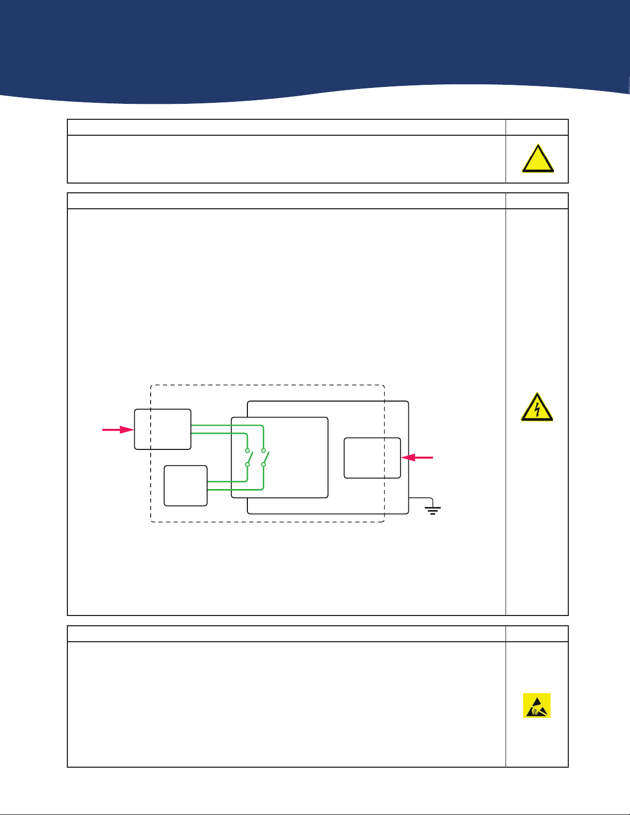
Diagram Showing Separation Between The Mains Circuit and Secondary Circuit / DUT
For the purposes of this document, a Mains Circuit is an installation classified as Overvoltage Category II up to
300V. Separation between the Secondary Circuit and Mains Circuit is achieved by a transformer in which the
primary windings are separated from the secondary windings by reinforced insulation, double insulation, or a
screen connected to the protective conductor terminal.
Switching
Module
Device
Under Test
Power
Supply
Power
Supply
Host Chassis
Secondary Circuit
Mains
Circuit
Mains
Circuit
Mains/Factory
Safety Ground
Page (vii)
CAUTION - Product Documentation Symbol
Suitably qualified & trained users should ensure that the accompanying documentation is fully read
and understood before attempting to install or operate the product.
!
Safety Instructions
Safety Instructions
All cleaning and servicing requires the equipment to be isolated and disconnected from the power source and user I/O
signals (refer to the Maintenance Section).
• Appropriate manual handling procedures should be followed as dictated by the weight of the individual module or the
combined weight of the modules & chassis.
• Should a fault occur with the module or chassis, immediately isolate and disconnect the incoming power to the chassis
and the user I/O signals.
• Ensure the equipment is installed, operated and maintained by trained and authorised personnel.
• For suitably equipped products in the event of an emergency press the red “emergency stop” button situated on the
front of the unit.
Page 1.1
pickeringtest.com
Section 1 - Technical Specification
Updated Product Information
The 40-575A and 40-576A have been introduced as a “form & fit”
update to the 40-575 and 40-576 respectively, the changes are to
provide an updated bus interface which will require the use of an
updated software driver. Otherwise, the electrical performance is
very similar and the pinout is identical.
X2
X4
X8
X1
X3
X5
X6
X7
Y1
Y2
X12
X9
X10
X11
X14
X16
X13
X15
X17
X18
X19
X24
X22
X23
X21
X20
X25
X26
X27
X32
X30
X31
X29
X28
X34
X36
X40
X33
X35
X37
X38
X39
X44
X41
X42
X43
X46
X48
X45
X47
X76
X74
X75
X73
X72
X77
X78
X79
X84
X82
X83
X81
X80
Matrix
Crosspoint
Y3
Y4
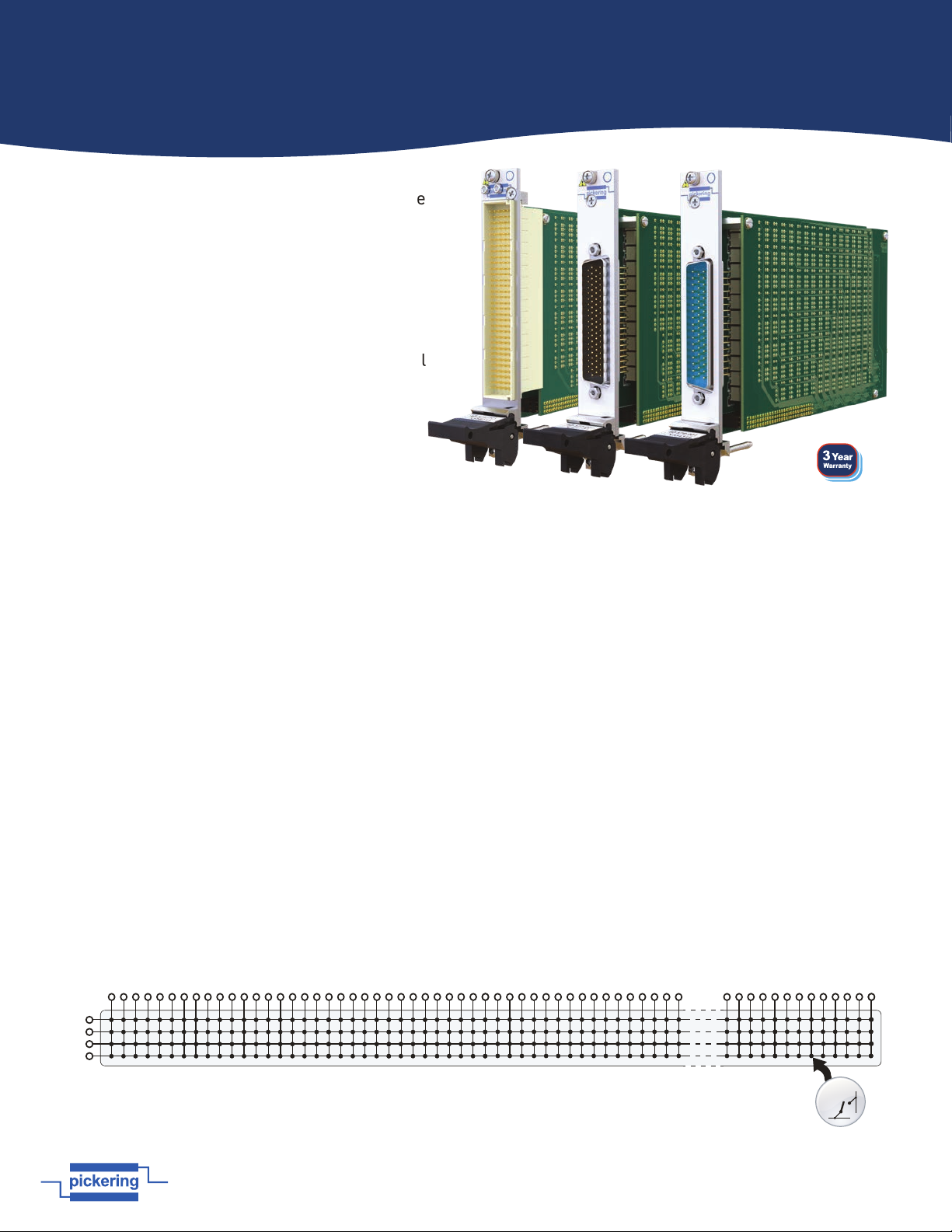
84x4, 1-Pole Matrix, Part Number 40-575A-001
The 40-575A-001 supports 4 concurrent switch paths for X to X and Y to X connections, however
connections between different Y axis lines (e.g. Y1 to Y2, Y3 or Y4) are not permitted by the driver.
Supported by
eBIRST
eBIRST switching system test tools simplify switching system
fault-finding by quickly testing the system and graphically
identifying the faulty relay.
For more information go to: pickeringtest.com/ebirst
y Highest Density Single-Slot 3U PXI 2 A 1-Pole
Matrices With up to 448 Crosspoints
y 84x4, 64x6, 50x8, 36x12 & 28x16 Options
y Maximum Current 2 A Hot or Cold Switching
y Switch up to 300 VDC/250 VAC and up to 60 W
Max Power
y Uses Gold-Plated Contact Electro-mechanical
Relays
y Relay Cycle Counting Included for
40-575A & 40-576A
y Drivers Supplied for Windows & Linux,
Plus Support for Real-time Systems
y Supported by PXI or LXI Chassis
y Supported by
eBIRST
™ Test Tool
y 3 Year Warranty
The 40-575A/576A/577/578/579 are a range of high density
matrix modules able to switch up to 2 A or 300 VDC/250 VAC.
They are constructed using high quality electro-mechanical
relays for high switching confidence.
The range is as follows:
• 40-575A-001 84x4, 1-Pole Matrix
• 40-576A-001 64x6, 1-Pole Matrix
• 40-577-001 50x8, 1-Pole Matrix
• 40-578-001 36x12, 1-Pole Matrix
• 40-579-001 28x16, 1-Pole Matrix
The modules are designed for switching medium voltage
and power signals. The user signal connection is via a
robust 160-pin DIN 41612, 78-pin D-type or 50-pin D-Type
connector that is fully supported by the wide range of
Pickering Interfaces cable and connector accessories.
Relay Cycle Counting
To aid with module “health” monitoring, the 40-575A and 40-576A
are provided with a relay cycle counting cycle feature. The
number of operations per contact are stored on the module and
can be used to determine if a relay is approaching EOL. This
information could allow system connections to be revised so that
signals applied to heavily used contacts are swapped with lightly
used contacts to prolong the working life of the relay(s).
pickeringtest.com
40-575A/576A/577/578/579
PXI Ultra High Density Matrix
Issue 2.2 July 2025