Technical_reference.pdf - 第12页
Technical Service Manual 12 Revision Dat e: August 2004 CONVEYOR OVERVIEW The elec trical portion of the Conveyor Sy stem c onsists of three m ajor com ponents: 1. The DRIVE MOT OR, which dr ives the belt and/or chain, s…
Technical Service Manual 11 Revision Date: August 2004
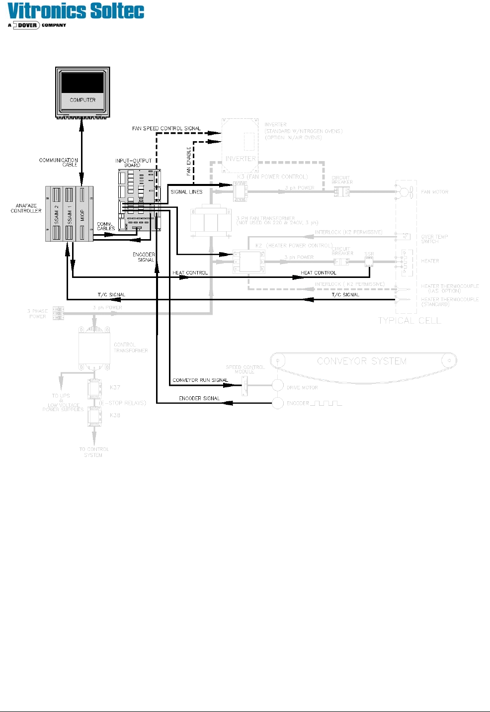
COMPUTER AND CONTROLLER OVERVIEW
Control of the oven is accomplished by:
1. An IBM ™
compatible COMPUTER runs the Oven Control Program. The computer has a serial communication link
with the CONTROLLER on the electrical panel.
2. The CONTROLLER interprets the Computer’s requests to energize, de-energize, or modulate devices or sub-
systems within the oven, then receives or sends the necessary signals. If the required signal (in or out) is 5VDC or
less, it is handled directly by the CONTROLLER. If a 120VAC output signal is needed, the CONTROLLER
communicates with the INPUT / OUTPUT BOARD. The I/O board relays will switch the necessary power for
operation.
Technical Service Manual 12 Revision Date: August 2004
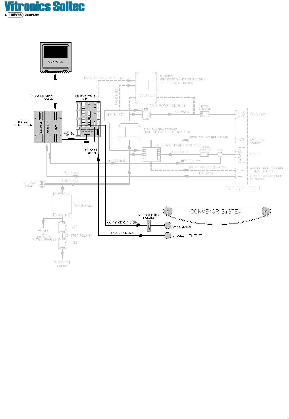
CONVEYOR OVERVIEW
The electrical portion of the Conveyor System consists of three major components:
1. The DRIVE MOTOR, which drives the belt and/or chain, shafts, and sprockets through a mechanical clutch.
2. The SPEED CONTROL MODULE, which:
A. Receives a 120VAC CONVEYOR RUN SIGNAL from the INPUT/OUTPUT BOARD.
B: Receives a modulated analog DC CONVEYOR SPEED SIGNAL from the CONTROLLER.
C: Sends a variable voltage output to the MOTOR.
3. The ENCODER, driven by the CONVEYOR, which sends a known number of pulses to the CONTROLLER for
each revolution of the conveyor drive shaft.
(10,000 pulses/rev for Stepper Drive Motors and 1,200pulses/rev for Analog Drive Motors)
Technical Service Manual 13 Revision Date: August 2004
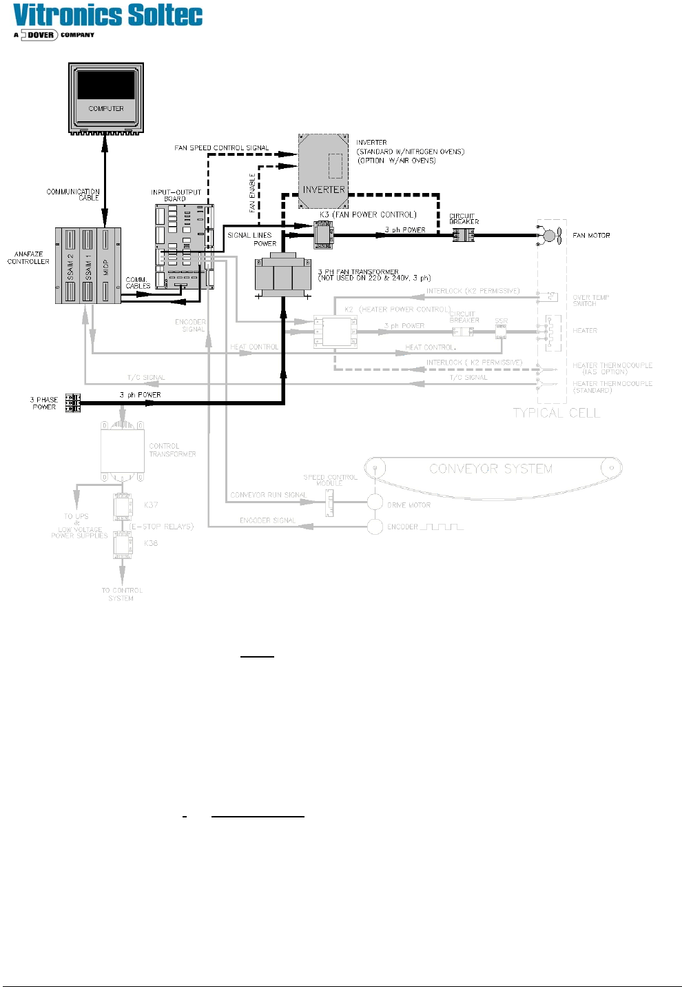
FAN CONTROL OVERVIEW
1) POWER SOURCE:
3 Phase power is provided to either the line terminals of the Fan Contactor (K13), the primary side of the
INVERTER, or 3 phase Fan Transformer, or the 3-phase line filter depending on the Oven options and Operating
Voltage.
2) CONTROL ELEMENTS:
Air-Only Ovens:
FAN CONTACTOR (K13) coil is energized by I/0 Board Output Relay A1-K2, K13’s contacts close, 3 phase
power is permitted to flow to/through the Fan CIRCUIT BREAKER(s). (F41 for all upper Fans & F42 for all lower
Fans) to the Fans for Full-Speed On/Off Control.
Nitrogen Option Ovens:
FAN CONTACTOR (K13)
does not exist. I/0 Board Output Relay A1-K2, in this case, serves as the Enable
input to the INVERTER. An analog (modulated) Low Voltage D.C. output from the CONTROLLER signals the
INVERTER to vary it’s output frequency to the Fans, resulting in variable-speed Control of the Fans.
3) FANS:
The FAN MOTORS are Open Frame, 3 Phase, 50/60 Hz, 1/6 Hp, 2800-3400 RPM @ rated frequency,
continuous duty.