Technical_reference.pdf - 第86页
Technical Service Manual 86 Revision Dat e: August 2004 COMPUT ER SYSTEM The c omputer system m ust be s et up and connected to the Vitronic s-Soltec O ven. The m onitor and k eyboard are placed on the swing arm / light …
Technical Service Manual 85 Revision Date: August 2004
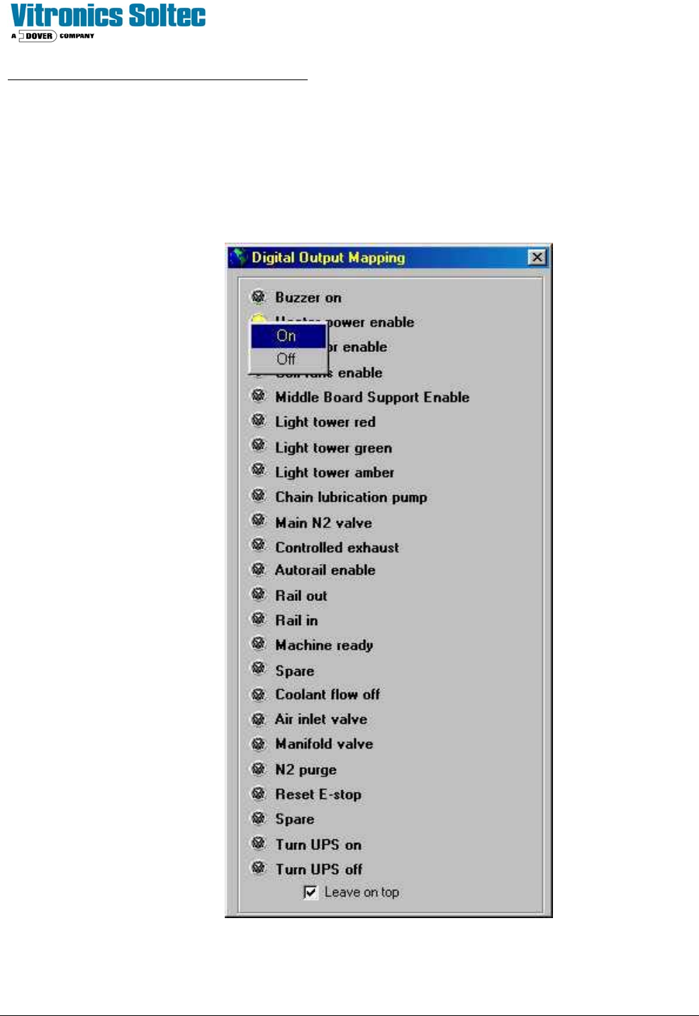
CONTROLLER OUTPUTS (Input/Output board)
The Input/Output board provides the ability to switch 120 VAC power through interposing relays. The Oven controller
controls the output status of the Input/Output board. Current limiters are installed on all conductors that supply power to
motors. As a diagnostic tool, the Input/Output board outputs may be manually activated one at a time.
See: “Checking Digital Output Status” in the Oven Operation Program.
NOTE: OPEN HEATER CIRCUIT BREAKERS BEFORE TESTING “Heater Power Enable”

Technical Service Manual 86 Revision Date: August 2004
COMPUTER SYSTEM
The computer system must be set up and connected to the Vitronics-Soltec Oven. The monitor and keyboard are placed
on the swing arm / light tower. The keyboard, monitor, and computer connect together. The connections on the back of
the computer are color coded, and they are different sizes/shapes to help connect them properly. (If the keyboard/mouse
does not function, swap the two connectors on the back of the Computer.)
One data cable must be connected from the computer to the oven.
Two 120VAC power cables (they are identical) are factory-wired for the Computer and Monitor. Plug the power cables
into the receptacles on the rear of the Computer and Monitor.
CONTROL CIRCUIT
Test procedure for safety interlock circuit
Þ Activate all circuit breakers.
Þ Ensure all E-stop switches are pulled out.
Þ Log into the Oven control Program and reset the E-Stop Alarm
Þ The E-stop relays K37 & K38 should be energized. If not, check the output of the control transformer using a
Voltmeter at wires #3 and #2. If voltage is present, but K37 & K38 are not energized, there is a break in the series
connection of safety interlocks.
Þ Check that each E-stop and safety interlock switch de-energizes K37 & K38.
Note: The enclosure safety interlock switches mentioned above are optional and do not exist on all ovens.

Technical Service Manual 87 Revision Date: August 2004
ELECTRICAL GROUNDING OF OVEN
GENERAL:
1) All ground wires have green or green/yellow insulation. Ground wires without green or green/yellow insulation
are identified using green or green/yellow tape.
2) The main electrical panel has a single ground terminal. All grounds must be connected to the ground
terminal.
3) Bare copper grounding wire inserted into an aluminum grounding block should be coated with an oxidation
inhibitor. Copper to aluminum has a natural galvanic reaction, which will degrade the electrical connection in
a short time. Inhibitor is not required when ferrules are used.
4) Use long nose pliers when inserting a ground wire into a double layered ground block. Insert the wire
completely into the block for a proper ground bond.
5) Ground blocks should be mounted on a clean and paint free surface. Use a star washer under the mounting
screws.
Test procedure for system ground continuity
1) Check continuity between the main ground terminal of the oven and the ground terminal on the mains
connecting plug or distribution board using an Ohmmeter.
2) Check continuity from the mains ground terminal of the oven to each individual component using an
Ohmmeter.
3) The resistance values should not exceed one Ohm.
Test procedure for insulation leakage (MEGGER [or Resistance] TEST)
1) Disconnect the system from the mains supply
2) Connect the three phases together at the mains supply connection point on the oven.
3) Disconnect the Circuit Breakers supplying the control circuit transformer and the circuit breaker supplying
the inverter.
4) Disconnect the computer and all peripheral equipment from the oven.
5) Connect an insulation test meter between one of the three phases and the ground connection point.
6) Turn on the Main Disconnect and test the system insulation for leakage at twice the single-phase voltage.
For example, for 240 VAC phase to neutral, check insulation at 500 Volts.
7) The resistance should be at least 1 MegOhm.