Technical_reference.pdf - 第99页
Technical Service Manual 99 Revision Dat e: August 2004 HOODLIFTS ) Standard, (installed on all ovens ) ! An option, (NOT installed on all ovens ) Operation; The elec trom echanical ac tuators rais e and lower the Hood (…
Technical Service Manual 98 Revision Date: August 2004
AIR MODE-
The N2 solenoid and the Compressed Air Solenoid will toggle, following the selection of an Air profile by the operator. All
gas flows in the oven remain identical to the N2 Mode, except that Nitrogen is replaced with compressed Air. Flow ratios
and all other process parameters remain identical.
MAINTENANCE
The Flux Flow Control system is virtually maintenance free if operating properly. To ensure this, it is recommended that
the inlet tube from the Flux Flow Control manifold into zone 1 be checked periodically (every six months) for flux residue.
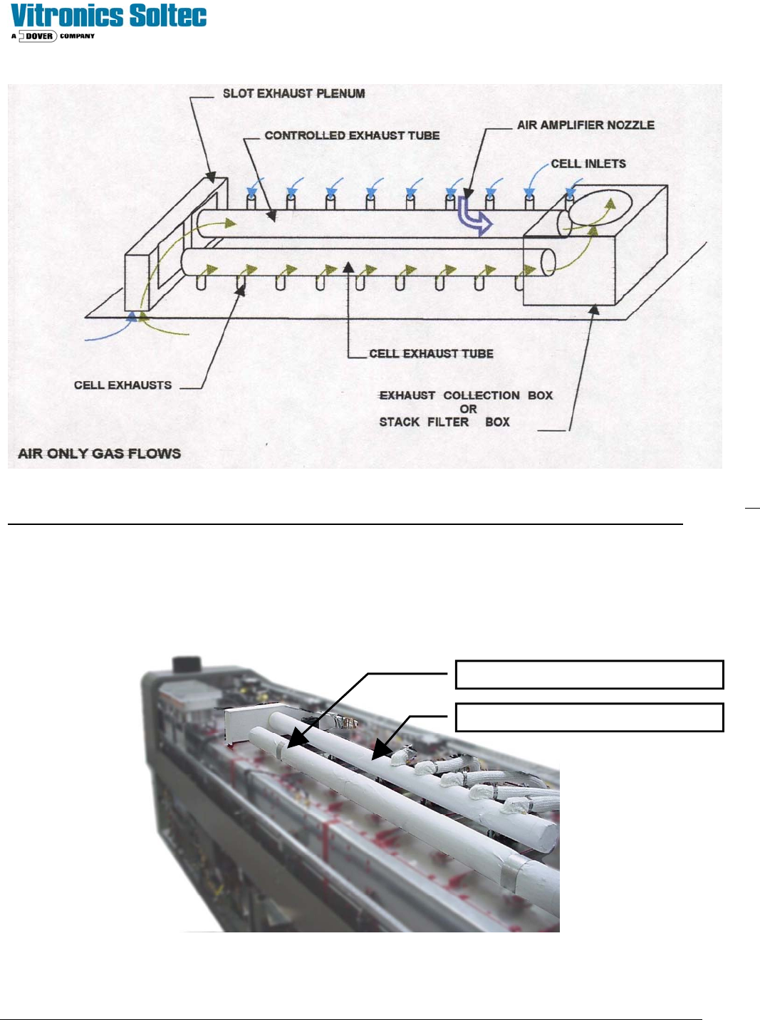
The Flux-Flow Control System is located under the sheet metal skins at the top of the Oven:
Individual Zone Exhaust Duct
Flux Flow Control Duct
Technical Service Manual 99 Revision Date: August 2004
HOODLIFTS
) Standard, (installed on all ovens) ! An option, (NOT installed on all ovens)
Operation;
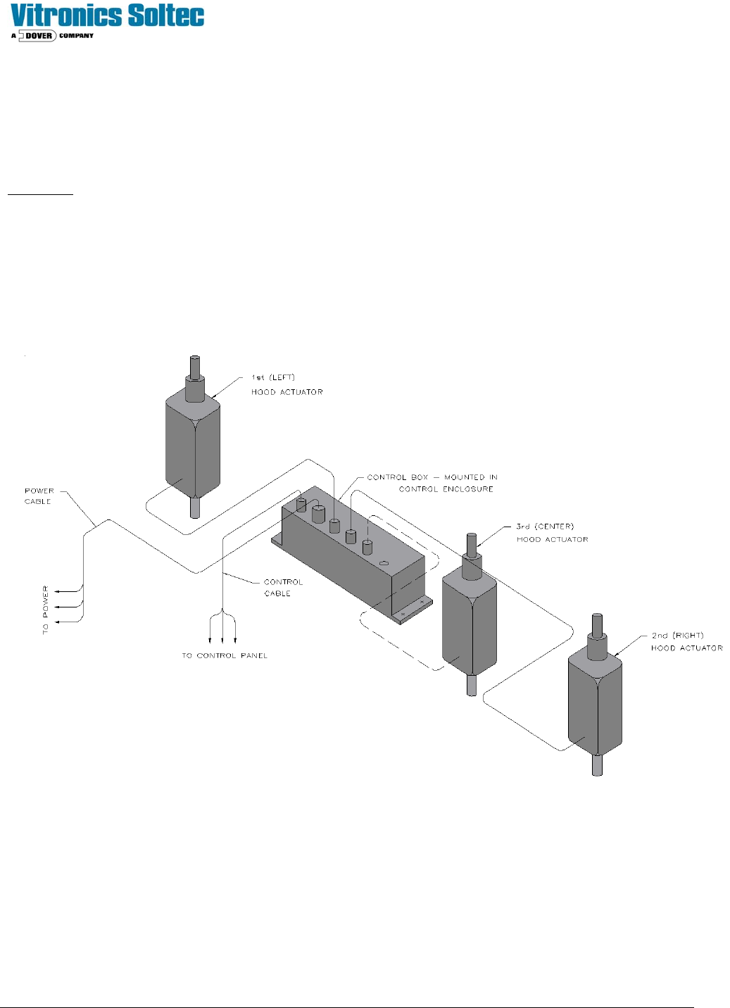
The electromechanical actuators raise and lower the Hood (including the upper heat zones of the oven). All models of
Vitronics-Soltec Reflow Ovens have 2 or 3 (depending on oven size) LINAK hoodlift Actuators with a LINAK control box
directly wired to the HOOD UP and HOOD DOWN selector switch on the oven operator control panel. The general
arrangement of the LINAK Actuators is shown here. A UPS option is available to permit opening the Oven Hood in the
event of a power failure.
Technical Service Manual 100 Revision Date: August 2004
ACTUATOR REMOVE AND REPLACE PROCEDURES
Removing the actuator assembly when the actuator has failed in the open position:
Stack wooden blocks/boards under the hood (where the actuator is connected to the hood), to keep the hood open when
the actuator is removed. Be careful to make the stack of wood stable.
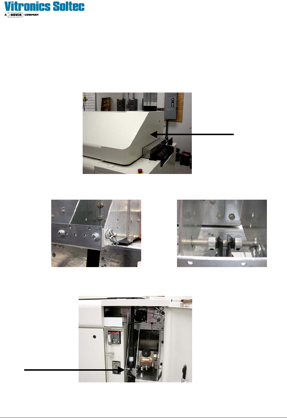
Remove the bonnet bridge sheet metal piece on the end of the oven where the actuator will be changed.
Remove the two safety clips from the pin holding the actuator piston to the bracket. Remove the piston pin holding the
actuator piston to the bracket. You may need to exert some pressure on the inner hood assembly to remove the pin.
The body of the actuator is accessed through the equipment cabinets on each end of the oven.
Unplug the actuator from the control box and remove the actuator
cable with the actuator.