Technical_reference.pdf - 第92页
Technical Service Manual 92 Revision Dat e: August 2004 INITIAL SETUP The f ollowing process is done at the tim e the oven is built. It should be required only after repair or servic e of the Autolube Sy stem . 1. Locate…
Technical Service Manual 91 Revision Date: August 2004
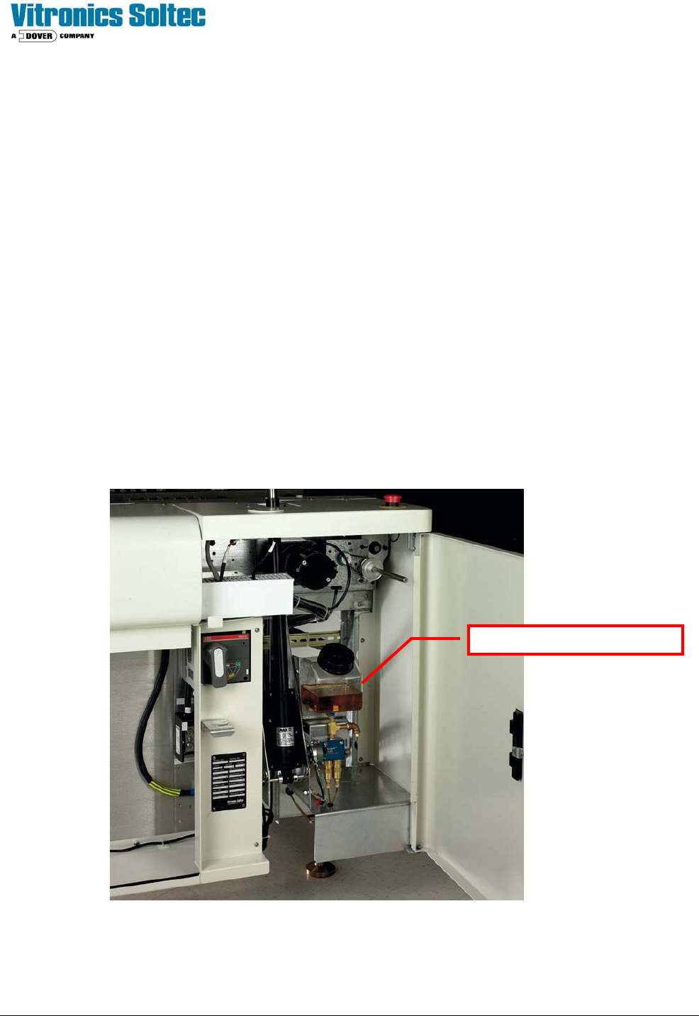
AUTO CHAIN LUBE TANK/PUMP ASSY
Operation:
The lubrication pump motor speed is 1 rpm with a displacement of .06cc per stroke (rev). The pump will supply 1 drop of
oil to the chain for each minute of conveyor chain travel. Therefore: if the conveyor is traveling at 14 in/min, 1 drop will be
placed on the chain every 14 inches. (A lube is done at whatever speed the conveyor is running at that time). A “Lube
Cycle” duration is (manual or automatic) is two complete chain cycles.
Priming:
Priming the system through the software can be very time consuming because of the low displacement of the pump... it
is best to use an oil can (not supplied with oven) to do most of the priming.
Priming should only be necessary after:
1. Servicing the autolube system
2. The reservoir has been allowed to run dry and air has been pumped into the lube lines
Location:
The Lubrication Tank-Pump Assembly is mounted to the frame at the front of the oven, inside the utility cabinet, at the
exit end of the oven. Opening the cabinet will expose the Lubrication Tank-Pump Assembly mounted on the Oven
Frame:
CHAIN LUBE RESERVOIR

Technical Service Manual 92 Revision Date: August 2004
INITIAL SETUP
The following process is done at the time the oven is built. It should be required only after repair or service of the
Autolube System.
1. Locate the lubrication reservoir. ( see illustration above )
2. Fill the reservoir with the lubricant, Darmex (Vitronics-Soltec P/N 1227204). (Remove the cap and pour the lubrication
into the top of the reservoir.
3. Prime the lube system. Refer to the User Manual (Chain lubrication system setup) for details on how to prime the
system.
4. Priming the autolube system can take as much 6 hours depending on the size of the oven. The priming operation will not
shut-off automatically, therefore it MUST be monitored to prevent excess oil from dripping on the floor.
(During normal “Manual” & “Auto” Lube operations, the system does stop automatically)
NORMAL OPERATION
First, refer to Rail Chain Lubrication in the User Manual.
To perform a single manual lubrication of the conveyor chain:
1. Select manual lubrication in the Oven Control Software by clicking on the Oil cans Icon. The conveyor chain will run, and
lube oil will be applied at the rate of 1 drop per 3 feet of chain, for two complete cycles of the chain(s).
For automatic lubrication of the conveyor chain on a regular basis:
1. Select automatic lubrication in the Oven Control Software. Enter the desired lube frequency. (The default is 275.) This is
the number of chain cycles between lubes.
2. Enter the lubrication alarm count. (The default is 50.) This is an estimate of the number of lubrications contained in the
oil reservoir. Observe the amount of oil used for 50 oiling cycles and then adjust the number up or down depending on
the amount of oil remaining in the reservoir only after refilling the reservoir
In automatic mode, the lubrication process does not interrupt oven processing.
The chain will be lubed while there is product in the oven.
Avoid “over oiling” and getting lubricant on the conveyor chain transport pins. Apply the lubricant sparingly, do not soak
the chain or apply so much that the lubricant drips off. Make sure the factory exhaust system is on and operating
properly because some fumes may be created once the heaters are turned on
ALARMS:
Þ When the alarm count for lubrications has been reached a “Low Oil Message” will be displayed at the bottom of the
Operating Screen. Automatic or manual lubrication will not be permitted until the reservoir has been filled, and the
alarm reset.
This is the best time to adjust the cycles between lubes and/or the number of lubes before “Low Oil Message alarm.

Technical Service Manual 93 Revision Date: August 2004
BOARD SUPPORT
Board Support is:
! Standard, (installed on all ovens) ) An option, (NOT installed on all ovens)
The Board Support is a precision flexible metal belt carrying vertical pins positioned under the Printed Circuit Board during
the process through the oven. The adjustment of the location of the belt under the product is driven by an electric motor.
A selector switch on the operator’s panel operates the motor. If the Board Support is not required for a particular product,
it can be positioned between the fixed rail pin chain. The free space required is 8 mm on one side of the Printed Circuit
Board, facing the Operator.
There must be a clear space of 3mm (1/8 inch) on the bottom side of the PCB for the pins of the CBS.
CONTROLLED COOLING
Controlled Cooling is:
!Standard, (installed on all ovens) )An option, (NOT installed on all ovens)
DESCRIPTION:
The Controlled Cooling System consists of two independent cooling circuits on the oven. The cooling circuits operate by
recirculating a cooling fluid through gas-to-liquid heat exchangers in the cooling cells of the oven and through liquid-to-air
heat exchangers external to the process tunnel of the oven. By adjusting the liquid temperature of the coolant with a
circulation heater and by controlling the external cooling fan, the gas temperature in the cooling cells of the oven can be
controlled.
CONTROL:
The operator interface for adjusting controlled cooling zone setpoints is the same as for the heated zones of the oven. A
controlled cooling equipped oven has two cooling cell setpoints, which can be changed by the operator within the Oven
Control Program. An oven with two cooling zones has a set point for each. An oven with three cooling zones has a set
point for the first and second cooling zones (the first cooling zone being the one closest to the heated section of the
oven). An oven with four cooling zones has a set point for the first and third zones.
OPERATION & PROCESS:
Controlled Cooling provides the ability to stabilize the temperatures in the cooling zones of the oven. It provides
compensation for factors such as changes in ambient temperature and product loading. It also allows the cooling zones
to reach a stable temperature much sooner than is possible with uncontrolled cooling, and ties the cooling zone
temperatures to the process ready condition of the oven.
The temperature range which is attainable for Controlled Cooling zones is influenced by many factors, including, but not
limited to, the following: heated zone set-points, conveyor type, conveyor speed, product loading, nitrogen flow settings,
machine exhaust, controlled exhaust setting, etc.