Technical_reference.pdf - 第72页
Technical Service Manual 72 Revision Dat e: August 2004 B. Convey or speed can be calibr ated to specif ic requir ements . This takes practic e, but can yield greater speed accur acy. C. The c onvey or speed should be m …

Technical Service Manual 71 Revision Date: August 2004
DC DRIVE CALIBRATION
1. Definitions-
A DC drive is actually a DC voltage amplifier. A small signal is sent to the drive and a large voltage is sent to the
motor. The typical DC drive uses an AC power source of 120 or 240 volts.
The set of controls found on a DC drive is:
A. Minimum speed adjust
B. Maximum speed adjust
C. IR comp
D. Torque
E. Signal
2. What do the controls do?
A. Minimum speed adjust -- adjusts the minimum voltage output of the DC drive at the minimum-input value.
This value is typically 0 - 10% of the maximum input voltage.
B. Maximum speed adjust -- adjusts the maximum voltage output of the DC drive at the maximum input
value. An experienced individual might set the input voltage to 100% of range and set the output to 80 -
90 volts. When in doubt, set the maximum output of the DC drive to 100 - 130 volts.
C. IR comp -- this adjusts the feedback circuit from the output of the DC drive. If the output voltage drops,
the IR comp circuit senses the drop, and more power is fed to the motor. This function is preset to a
value that covers 90% of all applications.
D. Torque -- this limits output current, and should only be adjusted by experienced people.
G. Signal -- signal adjust is found on DC drives which provide an option of being controlled by a computer. If
the DC drive is adjusted by a speed control potentiometer, signal or signal adjust has no function.
A DC drive with computer control will have a signal/manual selector switch or jumper. If the input does
not match the input selected, the DC drive will not operate correctly.
If a computer controls the DC drive, the maximum adjustment potentiometer will have no function.
3. How to make adjustments
The output of a DC drive is linear. The speed of rotation of a permanent magnet DC motor of less than one half
horsepower is not.
Install the new DC drive and operate the conveyor for one half-hour. This warms up the components on the DC
drive and the motor. Calibrating before a one half-hour warm up period will require a second calibration.
A. Set the input of the DC drive to 0%. Use the minimum speed adjustment to establish the minimum
speed at 1 to 2 inches per minute. Most systems will require a minimum of 5 to 7 inches per minute.
B. Set the input of the DC drive to 100%. Set the output voltage to the motor to 90 volts. Experienced
people may set the output to a higher or lower value.
Initially set the “IR comp” at 12 O’clock, “Torque” at 10 O’clock, “Min Speed” at 10 O’clock, “Max
Speed” = Off, and “Signal Adj.” at 12 O’clock to begin.
4. Additional useful information
A. Always recalibrate when any component of a control system is changed.

Technical Service Manual 72 Revision Date: August 2004
B. Conveyor speed can be calibrated to specific requirements. This takes practice, but can yield greater
speed accuracy.
C. The conveyor speed should be measured with a stopwatch every sixty days.
D. Motor brushes wear out.
E. Calibration values may change with the age of the system.
F. Always record the adjusting potentiometer settings before replacing or calibrating a DC drive.
G. When replacing a DC drive, record the potentiometer settings; draw a sketch of the wire hookups; make
sure all wires have labels.
Technical Service Manual 73 Revision Date: August 2004
5. CALIBRATION PROCEDURE FOR MINARIK CONTROLS
Tools required:
Multimeter (auto-ranging)
Small non-metallic screwdriver
Speed indicator
Before connecting the power supply:
1. Set the two ‘Jumper’ to ‘signal’.
2. Set the MAX SPEED pot to full clockwise.
3. Set the MIN SPEED pot to full counter clockwise.
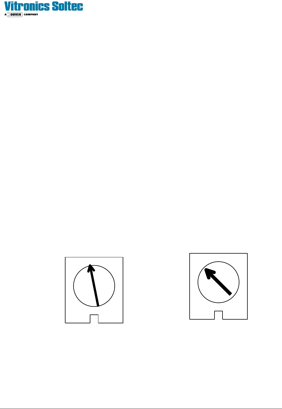
4. Set the IR COMP pot to the setting shown below.
5. Set the TORQUE pot to the setting shown below.
6. Set the signal Pot to full clockwise
With the power supply connected:
1. Set the multimeter to VOLTS AC and measure the input voltage to the control. If the voltage is less than
108V or greater than 132V disconnect the power supply and correct the supply voltage problem.
2. Disconnect the multimeter and set to measure VOLTS DC. Attach leads to the motor side of the control.
- In the Program Diagnostics, set the conveyor speed to 0%.
- Set the MIN speed pot so the conveyor is just barely moving.
3. Set the speed indicator on the front panel to 100 or full speed.
4. Adjust the MAX SPEED pot until the VOLTS DC equals the armature voltage listed on the motor
nameplate.
5. Check the speed of the conveyor.
6. Calibration is complete.
TORQUE IR COMP
MINARIK DRIVE POTENTIOMETER SETTINGS