Technical_reference.pdf - 第38页
Technical Service Manual 38 Revision Dat e: August 2004 CAUTION: DISCONNECT ALL POWER BE FORE TESTING Heater Resistance Check L ocations Read resistance with Ohm m eter acr oss these two term inals to check the heater re…

Technical Service Manual 37 Revision Date: August 2004
PROCEDURE:
1) Disconnect ALL POWER to the Oven.
2) Check for Tripped Heater Circuit Breakers, (F8 & F11 are not heater circuit breakers) If a circuit breaker is tripped
(open), (See 10, and 17 in the Heating System Diagnostic tree)
3) Open ALL Heater Circuit Breakers: F1-B to F12-B and F1-T to F12-T (Depending on Oven size, the highest CB No.
may not be 12 as shown in the illustration on the next page)
4) Perform Resistance Checks. See “HEATER RESISTANCE REFERENCE CHART” (Oven Type & Voltage must be
known) See “ HEATER RESISTANCE CHECK LOCATIONS” and connect Meter (M) on CBs and SSRs as shown.
A) If the resistance is “infinite” (open), the Heater may have a broken/disconnected wire or the heater element
may have an “open” in it.
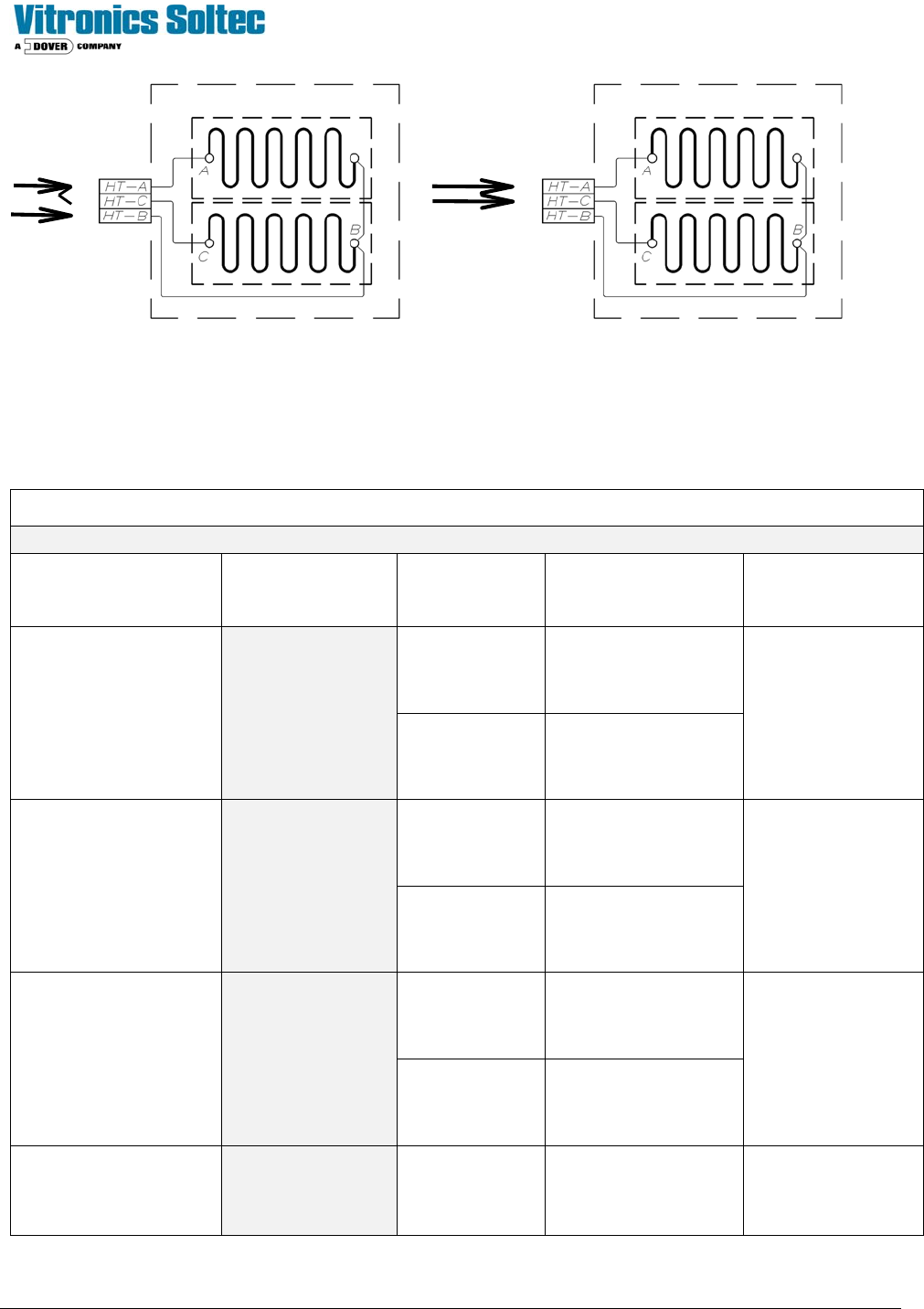
B) If the resistance on Parallel wired Heaters - (see “CHART”, Fig A)- is twice what it should be:
1. One Heater element may be “open”
2. One conductor from the Heater may be disconnected.
3. The jumper from term (1) to term (1A) may be missing or loose.
C) If the resistance is in agreement with the “HEATER RESISTANCE REFERENCE CHART”, then it is
reasonable to expect that the Heater and its conductors are in proper operating condition.
5) Close ALL Heater Circuit Breakers.
6) Refer to “HEATING - Problems and Possible Solutions” for other possibilities.
Technical Service Manual 38 Revision Date: August 2004
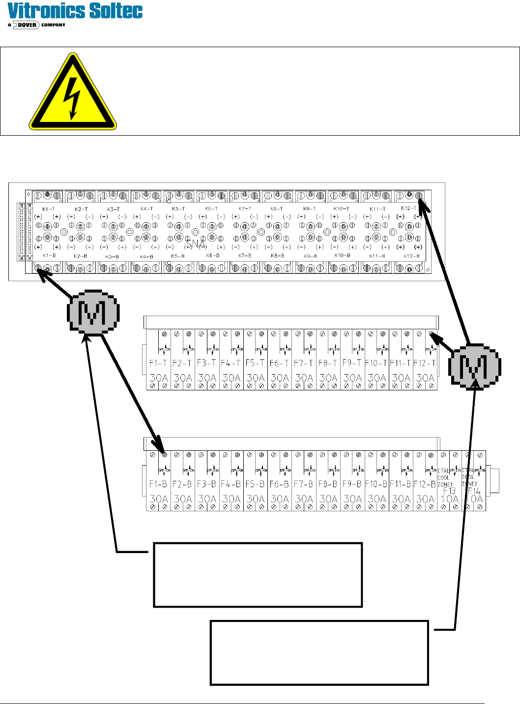
CAUTION:
DISCONNECT ALL POWER BEFORE TESTING
Heater Resistance Check Locations
Read resistance with Ohmmeter across
these two terminals to check the heater
resistance for Heater No. 1-B.
(Heaters 2B thru 12B are similar)
Read resistance with Ohmmeter across these
two terminals to check the heater resistance
for Heater No. 12-T.
(Heaters 2T thru 12T are similar)
Top Heater Circuit Breakers
Bottom Heater Circuit Breakers
Technical Service Manual 39 Revision Date: August 2004
Fig. A Fig. B
(Parallel) (Series)
XPM
2
Release Date: February 25, 2004
Heater Element Resistance Reference Chart
VOLTAGE RESISTANCE HOLE SIZE HEATER ASSY #
(
stamped on face plate)
ELEMENT #
(2 ELEMENTS PER
HEATER)
.136”
3085401
200 - 208 Volts
(LOW RANGE)
Test: 8.55 Ω - 9.45 Ω
9.0 Ω nominal
18.0 Ω = 1 open element
.170”
3160501
0866601
.136”
3085401
380 - 415 Volts
(LOW RANGE)
Test: 34.20 Ω - 37.80 Ω
36.0 Ω nominal
.170”
3160501
0866601
.136”
3085402
220 - 240 Volts
(HIGH RANGE)
Test: 11.40 Ω - 12.60Ω
12.0 Ω nominal
24.0 Ω = 1 open element
.170”
3160502
0904001
440 – 480 Volts
(HIGH RANGE)
Test: 45.60 Ω - 50.40 Ω
48.0 Ω nominal
.136”
3085402
0904001