Technical_reference.pdf - 第17页
Technical Service Manual 17 Revision Dat e: August 2004 OVEN CELL ARRANGEMENT The c ells are m ounted both above and below the conveyor, as shown, form ing a series of “Heat Z ones”. Each Heat Zone cir culates heat prim …
Technical Service Manual 16 Revision Date: August 2004
HEATING CELL DESCRIPTION
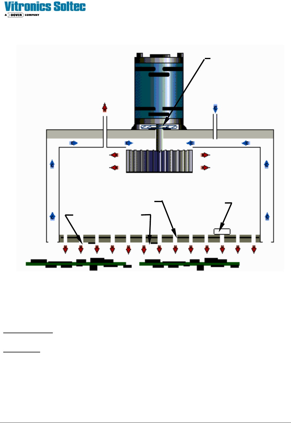
HEATING CELL CROSS-SECTION
CONSTRUCTION: The heat Cells are assembled and sealed as self-contained units with the Fan Motor, and Over
Temperature Switch mounted and wired to terminals, and the Thermocouples (1 or 2) mounted and wired to connectors.
OPERATION: The relatively thick heater assembly has a series of holes allowing heat transfer to the oven gases passing
from the Cell Cavity to the process tunnel.
Recirculation occurs through the low-pressure intakes at the sides of the Cell. These gasses are drawn into the cell
cavity, where they are passed through the heater and back into the process tunnel.
Fan Speed controls the velocity of the heated atmosphere, which influences the heat transfer to the PCB.
INSULATION
EXHAUST
FAN MOTOR
HEATER ASSEMBLY
THERMOCOUPLES
OVER TEMPERATURE
SWITCH
HEAT SLINGER
FAN BLADES
AIR OR
NITROGEN IN
Technical Service Manual 17 Revision Date: August 2004
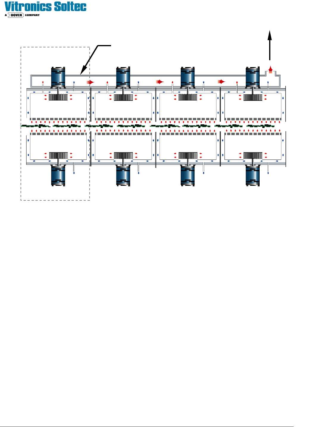
OVEN CELL ARRANGEMENT
The cells are mounted both above and below the conveyor, as shown, forming a series of “Heat Zones”.
Each Heat Zone circulates heat primarily within itself, thereby maximizing the thermal isolation between zones.
An insulated exhaust plenum mounted under the Bonnet collects gases from the individual upper heat cell exhausts and
conveys the combined flow to the Plant Exhaust System.
An oven contains several heating zones (5,7,8,10, or 12) and 2, 3, or 4 cooling zones. Cooling zones are identical to
heating zones except they have no heating elements and no exhausts (only gas intakes).
A properly operating oven is an inter-dependent system. When a heater or fan malfunctions, the balance and
performance of the oven as a system may be affected. Usually, an irregularity in operation could be the result of any one
(or more) malfunctions.
INSULATED CONTROLLED
EXHAUST PLENUM
TO PLANT
EXHAUST
SYSTEM
CELL 2BCELL 1B CELL 3B
CELL 4TCELL 3TCELL 2TCELL 1T
Zone 1

Technical Service Manual 18 Revision Date: August 2004
B - HEATING SYSTEM
In the following “Problems and Possible Solutions”, the most likely cause is listed first...investigate the most likely first,
then proceed to the next one in the list.
PROBLEMS AND POSSIBLE SOLUTIONS (The most likely cause is listed first)
HEATING PROBLEMS
OVER TEMPERATURE PROBLEM:
Not more than 10
o
C above set point and stable:
1. Temp drift from adjacent heater See: 1,2
2. Possible cell fan failure: See: 2, 3
Slow rise past set point:
1. Temp drift from adjacent heater See: 1, 2
2. Thermocouple problem in opposite heater See: 5
3. Radical recipe change See: 31
4. Short to ground in heater See: 8
Rapid rise past setpoint.
1. Latched control SSR See: 7, 12
2. Loose thermocouple wire See: 25
3. Controller Failure See: 11
4. Radical recipe change See: 31
5. DC stage of control SSR hot See: 4