Technical_reference.pdf - 第77页
Technical Service Manual 77 Revision Dat e: August 2004 Stepper Drive motor 0.8 inch/min ( 2.0 cm/min) 45.0 inch/min (114.3 cm/min) If the conveyor speed is not cons istent after running the c onveyor calibration routine…
Technical Service Manual 76 Revision Date: August 2004
2. Do the “conveyor calibration” described in the Oven Operation Program Manual after the clutch assembly is properly
adjusted.
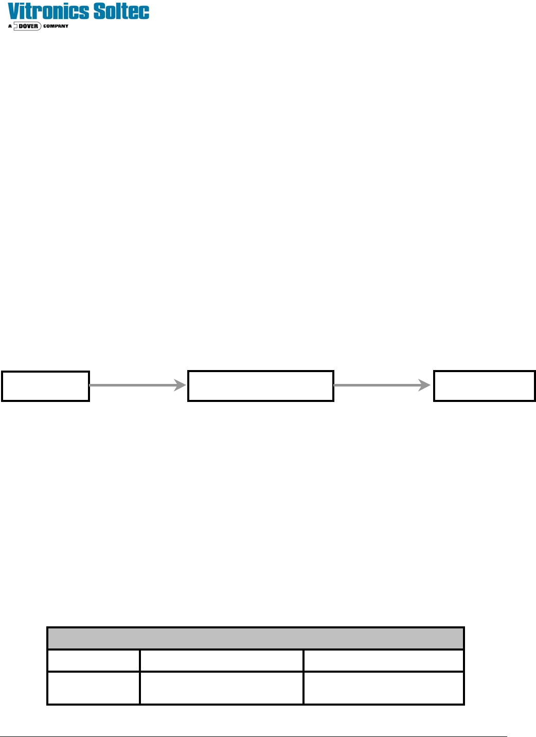
CONVEYOR DRIVE SYSTEM
The controller supplies an analog signal corresponding to the desired conveyor speed. The DC drive card sends an
amplified signal to the conveyor drive motor.
(The motor has a slip clutch connected to the conveyor shaft that drives the encoder.)
The encoder generates +5 VDC pulses as the motor drive system operates. The pulses go to the controller, which
modifies the analog signal to the DC drive card to compensate for any conveyor speed.
Set up the Conveyor Drive within the Oven Operation Program.
NOTE: This operation may require a password.
If the conveyor motor does not turn, check the following:
1 - Determine that K37 & K38 are energized
2 - Check for 120 VAC at the DC drive board (between terminals L1 and L2). If there is no 120VAC there, make sure that
A1-K12 is energized at the I/O board. Next, check the signal to the DC drive board. The signal should be +10 VDC
between DC drive terminals + and – signal input. If there is no signal at those terminals, make sure the oven
controller card cage is receiving +/– 15 VDC. If the cage is receiving +/– 15 VDC, but the drive is not receiving +10
VDC, there is either a wiring error or the DI board is faulty, or a poor wire connection.
3 - After all electrical signals are present and correct, adjust the IR COMP potentiometer to it's mid-point and adjust the
SIGNAL ADJUST potentiometer on the DC drive board to a level which produces a +90 VDC armature voltage
while under manual computer control. The armature voltage is measured between terminals A1 and A2 on the DC
drive board using a DC Voltmeter.
4 - At this point the MIN SPEED potentiometer should be adjusted to generate an armature voltage of approximately +12
VDC between terminals A1 and A2. This should keep the conveyor running slowly at a 0 VDC signal level.
5 - After the conveyor system has been tested, run the conveyor calibration routine in the Oven Control Program.
The conveyor system should be adjusted for the following speeds:
Conveyor Speed Table
MOTOR TYPE MINIMUM SPEED MAXIMUM SPEED
Analog Drive
motor
10.0 inch/min
( 25.4 cm/min)
75.0 inch/min
(178 - 203 cm/min)
MIOP
Oven I/O Board DC Drive
Ribbon Cable Round Cable

Technical Service Manual 77 Revision Date: August 2004
Stepper Drive
motor
0.8 inch/min
( 2.0 cm/min)
45.0 inch/min
(114.3 cm/min)
If the conveyor speed is not consistent after running the conveyor calibration routine, adjust the IR COMP potentiometer
of the conveyor drive up or down to compensate for the fluctuations.
ENCODER SERVICE & REPLACEMENT
Test procedure for encoder signal
To verify that the controller is receiving conveyor encoder pulses, run the conveyor at maximum speed. Monitor the
variable conveyor pulses. This should indicate the number of pulses received by the controller during the last scan
interval.
If the controller is not receiving pulses from the encoder, ensure that the encoder is receiving +5VDC (red wire at
encoder,) and that the wiring is correct. If all is correct, but the conveyor is still not functioning, next: monitor the encoder
pulses using an oscilloscope (wire #1016). If encoder pulses are present, the connection at the front of the DI board
could be faulty or the DI board could be faulty. Use of an oscilloscope should show a ‘square wave’.
A quick check to test for pulses from the encoder is to connect a DC Voltmeter between wires 1007 and 1016 and run the
conveyor. If a voltage level of approximately +1.2 VDC is measured, then pulses are probably being generated. A
voltage level of +5 VDC or 0 VDC indicate a possible fault with the encoder.
Oven I/O Board
Ribbon Cable
Oven I/O Board
1016 PX9-3 PX2-8 J4-6
TB1-15 Test Point

Technical Service Manual 78 Revision Date: August 2004
D- ELECTRICAL POWER & COMPUTER
CAUTION:
WHEN THE OVEN IS “OFF”, MANY PARTS OF THE OVEN
MAY BE ELECTRICALLY POWERED AND DANGEROUS
.
ELECTRO - STATIC DISCHARGE PROCEDURES ( ESD)
When any electronic PC board or any semiconductor device is to be handled, an antistatic wrist strap and an antistatic
work surface or mat must be used to reduce the possibility of causing damage to electronic components on the PC
board.
Semiconductor devices are sensitive to static electricity which can reach potentials of 20,000 volts or more. Static
electricity may reach 3000 volts before it can be felt ! If the discharge (spark) is visible, it is probably in excess of 5000
volts!
The current in static electricity is low. The component is usually weakened by the static damage, but does not fail
immediately. This causes intermittent problems, which can be very difficult to isolate. Static electricity can also cause
immediate failures on boards and components. Static failures from improper handling and packing can mask the original
problem from a repair person so that when you receive a board back from a repair facility, you end up with the same
problem you had before the repair.
Any clothing made with synthetic fibers is capable of generating static electricity. Any clothing can insulate a wrist
strap from your skin. The purpose of the strap is to discharge static electricity that has been built up on your body in a
controlled manner to prevent personal injury and damage to the equipment involved.
As long as you are properly connected to the oven ground by the antistatic wrist strap, you will be at the same
potential, as the oven and the risk of damaging the components with static electricity will be reduced.
When a board with electronic components on it is removed, it is important to remain connected to the oven.
When the board has been completely removed from the oven, it may be placed on top of the antistatic mat (connected to
the oven).
The board should be put into an antistatic bag while you are still connected to the oven. The bag should be 'sealed'
before disconnecting yourself from the oven ground.
Some antistatic bags are made of plastic that is coated on the inside with a thin conducting metallic film. This film turns
the bag into a “Protective Shield” surrounding its contents with a path for electricity to follow, thus preventing damage to
the contents when it is completely closed. (Torn bags should be discarded.).
The bags can hold a static charge on their outside surfaces. Always properly ground yourself and have a
properly connected antistatic work surface to rest the bag and contents on before opening an antistatic bag.
When replacing a PC board or electronic component, always be properly grounded until finished with the repair or
replacement procedure. Always be properly grounded to the oven that is being worked on. Not all ovens are at the same
ground potentials.
All electronic boards and components must always be properly protected from static electricity and properly
stored.