0197787-01_UM_HeadVerification_708_EN.pdf - 第31页
SIPLACE Head V erification User Manual Edition 01/2015 31 7. Segment 1 now m oves down wards again with travel profile TP34 [ T P34 LOW FORCE Z-AXIS] and determines the en d pos ition signal again as M easure 3 [µm] 8. T…

SIPLACE Head Verification
User Manual Edition 01/2015
30
The "Signal threshold" [µm] value is also the same for all segments.
A deviating value would indicate that the cover switching ring for the segment is not reliably or properly
triggering the light barrier.
4.3.4 Meaning of the Results
"Nozzle spring / Signal threshold" error at all segments:
1. Light barrier Z-down defective
Check and, if necessary, replace the Z-down light barrier
"Nozzle spring / Signal threshold" error at individual segments:
1. Segment spring is bent or mechanically damaged
Replace DP
2. The position, fixture or state of the cover switching ring is faulty
Check the fixture and, if necessary, replace the cover switching ring
4.4 "Z-Axis Movement" Measurement
The following tools are required for these measurements:
CPP: 12x nozzle type 2069 03094135-01 (vacuum nozzle red, closed)
CP20P: 20x nozzle type 4069 03106244-01 (vacuum nozzle red, closed)
CP20A: 20x nozzle type 1069 03094112-01 (vacuum nozzle red, closed)
4.4.1 Explanation of Measurement – Procedure
This measurement is used to determine the total Z travel path for a segment!
The maximum travel path determined indicates the state of the segment linear guide and also the Z
axis linear guide.
The Z axis moves with a special travel profile 3x in a free area for each segment.
The maximum travel paths determined indicate the state of the linear guides.
This proves whether each linear guide is free and has ease of movement, with no mechanical
blockages.
The results of these measurements provide feedback about the following sources of errors:
1. State of linear guide for individual segments
2. State of Z axis linear guide
Measurement steps:
1. A star and Z axis reference run is performed to bring the head into a defined initial position.
2. The head is positioned in a free area (reject bin).
3. Segment 1 is moved downwards with travel profile TP34 [TP34 LOW FORCE Z-AXIS].
This travel profile TP34 [TP34 LOW FORCE Z-AXIS] moves the Z axis downwards with low
force and creep speed.As soon as a mechanical resistance or difficulty in movement causes
an increase in the Z motor current, an end position signal is emitted.
In normal circumstances, an end position signal is emitted when the Z axis reaches the bottom
mechanical stop position.
The end position signal determined is saved as Measure 1 [µm] .
4. The Z axis then moves back up again using travel profile TP1 [TP1 ABSOLUT DEFAULT].
5. Segment 1 now moves downwards again with travel profile TP34 [TP34 LOW FORCE Z-AXIS]
and determines the end position signal again as Measure 2 [µm]
6. The Z axis then moves back up again using travel profile TP1 [TP1 ABSOLUT DEFAULT].
SIPLACE Head Verification
User Manual Edition 01/2015
31
7. Segment 1 now moves downwards again with travel profile TP34 [TP34 LOW FORCE Z-AXIS]
and determines the end position signal again as Measure 3 [µm]
8. The Z axis then moves back up again using travel profile TP1 [TP1 ABSOLUT DEFAULT].
9. The star steps to segment 2 and performs steps 3-8.
10. These sequences are also performed for all other segments.
11. The values "Measure 1" to "Measure 3" are used to calculate an average value, known as
End position Z [µm].
A value defining the theoretical maximum travel range is stored in the machines. If the
average value is within the tolerance range, the mechanics of the axes are understood to be
OK.
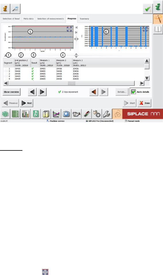
4.4.2 Explanation of Measurement Results in "Progress" Menu
After completion of the measurement, the following results appear in the "Progress" menu:
Figure 20: Z-axis movement results
Legend:
1. Segment measured
2. Calculated End Position Z in µm from the average value of all individual measurements
Measure 1 – Measure 3 (4).
This calculated end position must be within a tolerance (in our case 30300..30510µm) and
indicates the maximum possible Z axis travel path up to a constructive mechanical stop.
End position Z [µm] = (Measure 1 [µm] + Measure 2 [µm] + Measure 3[µm]) /3
3. Results display (OK green tick / NOK red X)
As soon as the Measure 1 – Measure 3 value or the average value End position Z are
outside the tolerance, the segment will be marked as faulty.
4. The results of the three Z axis movements with travel profile TP1 [TP1 ABSOLUT DEFAULT]
are entered here.Each result must be within the tolerance (in our case 30300..30510µm). If
this is not the case, this indicates that the segment guide has difficulty moving.
5. This diagram illustrates the End position Z values for the segments.
Blue line Average end position Z value [µm] for individual segments
Red border Min and max tolerances (in our case 30300..30510µm)
Use the button to zoom in on the diagram.
6. This diagram illustrates the Measure 1 – Measure 3 values for each segment.
3x blue column Measure 1 – Measure 3 [µm] per segment
SIPLACE Head Verification
User Manual Edition 01/2015
32
The top and bottom diagram borders are based on the dispersion of results for all "Measure 1"
– "Measure 3" values, which is why the deviation in bar lengths may be confusing!
Use the button to zoom in on the diagram.
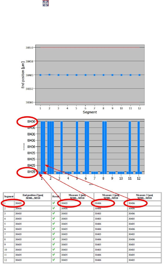
4.4.3 Explanation of Measurement Results Using Results PDF
These results can be seen if you scroll down the "Summary" menu or generate a results PDF!
Figure 21: Results PDF for Z-movement
The average values from the three Measure 1- Measure 3 values provides the End position Z value.
This value shows whether a segment can be easily moved along the entire constructive travel path.
The End position Z value and the three individual measurements Measure 1 – Measure 3 must all
be within the tolerance range. However, slight deviations are normal.
Our example shows that "Measure 1" has a value of 30405µm. "Measure 2" – "3" each have a value
for the travel range of 30406µm.
This difference can also be seen on the bar length in the diagram.
If either "Measure1", "2" or "3" is outside the tolerance, this indicates that the guide for this segment is
defective, as a repeated ease of movement can not be proven. The DP (for CP20P/A) or the segment
guide (for CPP) will need to be replaced soon.
If all "Measure1" – "Measure3" values are outside the tolerance range, this clearly indicates that the
guide has difficulty moving.The DP (for CP20P/A) or the segment guide (for CPP) must be replaced.