0197787-01_UM_HeadVerification_708_EN.pdf - 第60页
SIPLACE Head V erification User Manual Edition 01/2015 60 4.10.3 Ex planation of Measurement Results Using Results PDF These results can b e seen if you scroll down the "Sum mary" menu or generat e a results PD…
SIPLACE Head Verification
User Manual Edition 01/2015
59
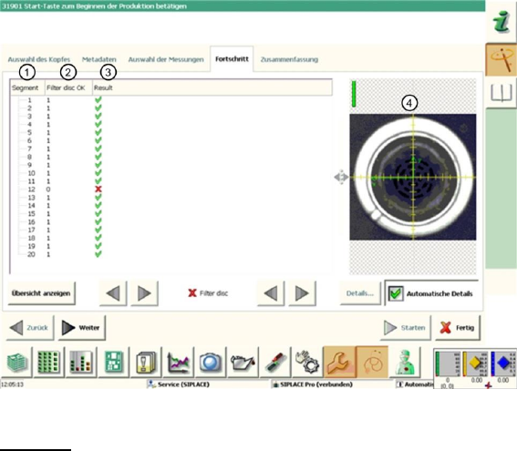
4.10.2 Explanation of Measurement Results in "Progress" Menu
After completion of the measurement, the following results appear in the "Progress" menu:
Figure 39: Filter disc result
Legend:
1. Segment measured
2. The "Filter disc OK" value is either 0 or 1.
If the segment is rotated over the component camera, the camera image will be evaluated with
a digital filter. The camera pixels are then compared with the settings in the digital filter.
If the rough filter disc structure is not recognized, the filter disc will be saved as "missing".
If too many light-colored pixels are found within the filter disc structure, the filter disc will be
saved as "dirty".
Both measurements will be combined.If one measurement fails, the "Filter disc OK" value will
be saved with 0, which means NOK (not OK).
If both measurements are OK, a value of 1 will be issued for "Filter disc OK".
3. The "Filter disc OK" value is illustrated again here.
Results display (OK green tick / NOK red X)
4. This shows the image with the digital filter over the camera image of the filter disc. The
structures saved in blue show recognized filter disc fiducials, which were detected by the
digital filter. When selecting the segments in the results overview, the corresponding
evaluation image is shown and the Vision dump shows whether the filter disc is missing or
"only" dirty.
Note: The Vision dumps are deleted after the PDF has been generated or after completion of
the head verification process ("done" button) and can therefore no longer be used for error
analysis.

SIPLACE Head Verification
User Manual Edition 01/2015
60
4.10.3 Explanation of Measurement Results Using Results PDF
These results can be seen if you scroll down the "Summary" menu or generate a results PDF!
Figure 40 Results PDF for filter disc
We can see here that the filter discs at segments 4 and 16 have been recognized as faulty. Sadly, the
overview does not reveal the cause of this. The camera image recorded (chapter 6.10.2 legend 4) has
been deleted after generating the PDF.
4.10.4 Meaning of the Results
Error at all filter discs:
1. Check the component camera for contamination
Error at individual filter discs:
1. Filter disc contaminated Replace the filter disc
2. Filter disc broken Replace the filter disc
3. Filter disc missing Insert a new filter disc
4. Filter disc missing at each test Check the filter disc pick-up the DP, to establish whether
there is damage Replace DP
4.11 "Z/DP Positioning" Measurement
The following tools are required for these measurements:
CPP: 12x nozzle type 2069 03094135-01 (vacuum nozzle red, closed)
4.11.1 Explanation of Measurement – Procedure
This measurement checks the deviation between the Z-down light barrier and the component sensor,
in accordance with the angle setting of the segment.
The results of these measurements provide feedback about the following sources of errors:
1. State of linear guide for individual segments
2. State and cleanliness of Z-down light barrier on segment (DP)
3. State of component sensor
Measurement steps:
1. The head is positioned over the height reference run position on the conveyor side.
SIPLACE Head Verification
User Manual Edition 01/2015
61
2. Segment 1 is moved downwards with travel profile TP5 [TP5 LIGHT BARRIER]. The segment
has the rotary angle 0°.
3. The component sensor is monitored during the downwards movement.
As soon as the component sensor is interrupted by the nozzle tip, this value is saved as CS
pos 1 [µm]. This is now the value for the Z axis path, when the nozzle interrupts the
component sensor at segment 1 mit 0°.
4. When the nozzle meets the height reference run position of the conveyor side, the spring is
compressed in the segment and the Z down light barrier is activated by the switching ring.
This position is emitted as the end position signal. The value is saved as Measure 1 [µm] for
segment 1 mit 0°
5. Segment 1 is moved upwards with travel profile TP1.
6. Segment 1 is rotated by 60° 60° absolute
7. Segment 1 is moved downwards again with travel profile TP5 [TP5 LIGHT BARRIER]. The
segment has the rotary angle 60°.
8. The component sensor is monitored during the downwards movement.
As soon as the component sensor is interrupted by the nozzle tip, this value is saved as CS
pos 2 [µm]. This is now the value for the Z axis path, when the nozzle interrupts the
component sensor at segment 1 mit 60°.
9. When the nozzle meets the height reference run position of the conveyor side, the spring is
compressed in the segment and the Z down light barrier is activated by the switching ring.
This position is emitted as the end position signal. The value is saved as Measure 2 [µm] for
segment 1 mit 60°
10. Segment 1 is moved upwards with travel profile TP1.
11. Segment 1 is rotated again by 60° 120° absolute
12. Steps 2-5 are performed again.
13. This is repeated for the other absolute angles 180° / 240° / 300° / 360°.
14. The following measurements are reached for segment 1
Rotary angle 0° Component sensor value CS pos 1 [µm] & Z-Down LS Measure 1 [µm]
Rotary angle 60° Component sensor value CS pos 2 [µm] & Z-Down LS Measure 2 [µm]
Rotary angle 120° Component sensor value CS pos 3 [µm] & Z-Down LS Measure 3 [µm]
Rotary angle 180° Component sensor value CS pos 4 [µm] & Z-Down LS Measure 4 [µm]
Rotary angle 240° Component sensor value CS pos 5 [µm] & Z-Down LS Measure 5 [µm]
Rotary angle 300° Component sensor value CS pos 6 [µm] & Z-Down LS Measure 6 [µm]
You now have measurements for a complete segment rotation, in 60° steps.
15. Steps 2-14 are now performed for all other segments.