0197787-01_UM_HeadVerification_708_EN.pdf - 第35页
SIPLACE Head V erification User Manual Edition 01/2015 35 4.5.2 Explanation of Measurement Results in Progress Menu After com pletion of the measurem ent, the following res ults appear in the " Progress" m enu:…

SIPLACE Head Verification
User Manual Edition 01/2015
34
Measurement steps:
1. The Z axis remains in the top position
2. All DPs are referenced so that they are at 0°.
3. Segment 1 is rotated into the placement position but remains in the top position.
4. Measurement 0°:
The Z-down light barrier is triggered and measures the distance to the cover switching ring for
segment 1.The Z-down light barrier provides an analog voltage value for the distance. This
value is known as Measure 1 [mV].
This 0° value is also used as a reference value for checking the general functionality of the
light barriers.This reference value is compared to a theoretical value in the machine data.
5. Rotate segment 1 to 90°
6. Measurement 90°:
The Z-down light barrier is triggered and measures the distance to the cover switching ring for
segment 1.The Z-down light barrier provides an analog voltage value for the distance. This
value is known as Measure 2 [mV].
7. Rotate segment 1 to 180°
8. Measurement 180°:
The Z-down light barrier is triggered and measures the distance to the cover switching ring for
segment 1.The Z-down light barrier provides an analog voltage value for the distance. This
value is known as Measure 3 [mV].
9. Rotate segment 1 to 270°
10. Measurement 270°:
The Z-down light barrier is triggered and measures the distance to the cover switching ring for
segment 1.The Z-down light barrier provides an analog voltage value for the distance. This
value is known as Measure 4 [mV].
11. The whole rotation of the cover switching ring is known as the Mounting variation [µm]
value.
This value is calculated using the minimum and maximum results for "Measure 1" – "Measure
4". The difference between the lowest and highest voltage value provides a value which
describes the eccentricity of the cover switching ring and the rotation of the cover switching
ring around the central axis of the DP (sway).
If this value is higher than a defined tolerance, this indicates that the cover switching ring is
not correctly fitted or that it is defective.
12. Measurements 4-11 are now performed for all other segments.
SIPLACE Head Verification
User Manual Edition 01/2015
35
4.5.2 Explanation of Measurement Results in Progress Menu
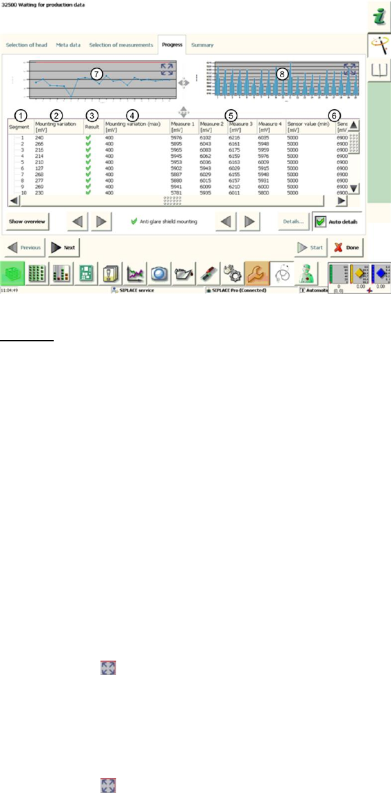
After completion of the measurement, the following results appear in the "Progress" menu:
Figure 22: Cover switching ring mounting result
Legend:
1. Segment measured
2. Calculated Mounting variation value in µm
This value describes the eccentricity (rotation) of the cover switching ring to the central axis
of the segment.
This value is calculated by finding the difference between the lowest and highest analog
voltage value for "Measure1"-"Measure4".
3. Results display (OK green tick / NOK red X)
4. This is the permissible threshold for eccentricity (rotation) of the cover switching ring. The
Mounting variation (2) value and the result (3) refer to this threshold.
5. Measure1 – Measure4 provide the analog voltage values for the light barrier measurement
and show the distance between the Z-down light barrier and the edge of the cover switching
ring at 0°, 90°, 180° and 270°.
6. The Sensor value (min / max) in µm gives the plausible permissible threshold values for
"Measure1" – "Measure4".
7. This diagram illustrates the Mounting variation values for the segments.
Blue line Mounting deviation in µm for individual segments
Red border Min and max tolerances (in our case 0..400mV)
Use the button to zoom in on the diagram.
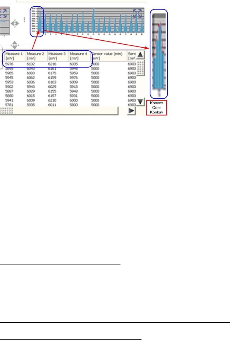
8. This diagram illustrates the "Measure1" – "Measure4" values for the segments.
Blue bar one bar each for "Measure1"(0°) – "Measure4" (270°)
If the light barrier works reliably, the bars should ideally be the
same height (100% concentricity) or convex/concave (eccentricity)
Red border Min and max tolerances (in our case 5000..6900mV)
Use the button to zoom in on the diagram.
4.5.3 Explanation of Measurement Results Using Results PDF
These results can be seen if you scroll down the "Summary" menu or generate a results PDF!
SIPLACE Head Verification
User Manual Edition 01/2015
36
Figure 23: Results PDF for cover switching ring mounting
The bar chart shows how far the cover switching ring rotates around the center of the segment.
The distance values "Measure1" (0°), "Measure2" (90°), "Measure3" (180°) and "Measure4" (270°)
are shown for each segment in the bar chart.
The values "Measure1" – "Measure4" are shown from left to right.
When the light barrier is functioning correctly and the cover switching ring is intact, the bars in the
chart must always have a convex or concave shape.
If the sequence short-long-short-long or long-short-long-short appears, this either indicates that the
light barrier is defective (due to inconsistent measurements) or that the cover switching ring is broken.
If the bar chart has a concave or convex shape but is still outside the tolerances, this indicates that the
cover switching ring is rotating towards the DP axis.
The reason for this could be incorrect fitting of the cover switching ring on the DP seat, that the DP is
running eccentrically (and is therefore damaged) or that the cover switching ring is damaged.
4.5.4 Meaning of the Results
"Mounting variation" error at all segments:
1. Light barrier Z-down defective
The "Measure1"-"Measure4" values are below the thresholds Replace the light barrier Z-
down and Z drive unit assemblies completely
2. Incorrect position of Z-down light barrier
Readjust the Z-down light barrier
3. Z-motor or linear guide of Z drive defective
"Measure1" – "Measure4" errors at multiple segments (not concave / not convex):
1. Light barrier Z-down faulty may have cable break Replace the Z-down light barrier
"Mounting variation" error at individual segments:
1. The "Mounting variation" (2) value is above the "Mounting variation maximum" threshold (4)
Cover switching ring not seated properly on DP or it has fractures
2. One or more "Measure1" – "Measure4" values are under the minimum "Sensor value"
threshold
Cover switching ring is dirty