0197787-01_UM_HeadVerification_708_EN.pdf - 第59页
SIPLACE Head V erification User Manual Edition 01/2015 59 4.10.2 Ex planation of Measurement Results in "Progress" Menu After com pletion of the measurem ent, the following res ults appear in the " Progres…

SIPLACE Head Verification
User Manual Edition 01/2015
58
4.9.4 Meaning of the Results
"Up X [µm]" and "Up Y [µm]" errors at all segments:
1. Check the star zero point correction
"Down X [µm]" and "Down Y [µm]" at all segments:
1. Z axis linear guide loose or defective Check or replace the Z motor
"Up X [µm]" / "Up Y [µm]" / "Down X [µm]" / "Down Y [µm]" at individual segments:
1.
Segment deformed, possibly after a crash Replace segment / DP
2. Linear guide DP/segment worn out Replace the DP / replace the linear guide for segment
4.10 "Filter Disc" Measurement
This measurement is only performed at the CP20A placement head.
This measurement is performed without nozzles on the segments
4.10.1 Explanation of Measurement – Procedure
This measurement checks the filter discs on the segments of the CP20A head.
These filter discs seal the interface between the DP and the nozzle, thereby guaranteeing a reliable
vacuum to the nozzle and protecting the vacuum cycle from contamination.
The machine first places all nozzles in the changer.
Then each segment has blast air of 400mbar applied to it.
This air blast should blow loosely fitted and damaged filter discs off the DP seat.
In addition, any strongly contaminated filter discs will be cleaned (with air blast).
then the segments are examined in order with the component camera, to check whether a filter disc is
fitted or whether it is contaminated.
A digital filter (mask) is placed over the camera image of the filter disc.
An algorithm is used to evaluate the degree to which the digital filter mask recognizes the structures of
the filter disc in the camera image.
A light-dark evaluation is performed. If the camera image is too light, compared to the value set in the
digital filter mask, the filter disc is recognized as missing. There is a threshold for " Filter disc present"
and for "Filter disc missing".
If this measurement was successful and the filter disc is recognized as present, the digital filter mask
is evaluated again and the software searches within the dark filter disc for light-colored pixels. These
light-colored pixels indicate contaminants.If these contaminants exceed a certain number of pixels
(pixel size), the filter disc will be marked as dirty.
The results of these measurements provide feedback about the following sources of errors:
1. Defective filter disks
2. Missing filter discs
3. Defective filter disc seat on the DP
SIPLACE Head Verification
User Manual Edition 01/2015
59
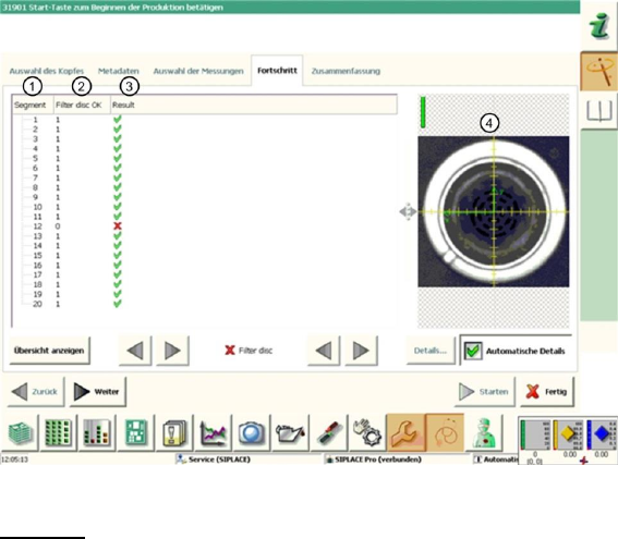
4.10.2 Explanation of Measurement Results in "Progress" Menu
After completion of the measurement, the following results appear in the "Progress" menu:
Figure 39: Filter disc result
Legend:
1. Segment measured
2. The "Filter disc OK" value is either 0 or 1.
If the segment is rotated over the component camera, the camera image will be evaluated with
a digital filter. The camera pixels are then compared with the settings in the digital filter.
If the rough filter disc structure is not recognized, the filter disc will be saved as "missing".
If too many light-colored pixels are found within the filter disc structure, the filter disc will be
saved as "dirty".
Both measurements will be combined.If one measurement fails, the "Filter disc OK" value will
be saved with 0, which means NOK (not OK).
If both measurements are OK, a value of 1 will be issued for "Filter disc OK".
3. The "Filter disc OK" value is illustrated again here.
Results display (OK green tick / NOK red X)
4. This shows the image with the digital filter over the camera image of the filter disc. The
structures saved in blue show recognized filter disc fiducials, which were detected by the
digital filter. When selecting the segments in the results overview, the corresponding
evaluation image is shown and the Vision dump shows whether the filter disc is missing or
"only" dirty.
Note: The Vision dumps are deleted after the PDF has been generated or after completion of
the head verification process ("done" button) and can therefore no longer be used for error
analysis.

SIPLACE Head Verification
User Manual Edition 01/2015
60
4.10.3 Explanation of Measurement Results Using Results PDF
These results can be seen if you scroll down the "Summary" menu or generate a results PDF!
Figure 40 Results PDF for filter disc
We can see here that the filter discs at segments 4 and 16 have been recognized as faulty. Sadly, the
overview does not reveal the cause of this. The camera image recorded (chapter 6.10.2 legend 4) has
been deleted after generating the PDF.
4.10.4 Meaning of the Results
Error at all filter discs:
1. Check the component camera for contamination
Error at individual filter discs:
1. Filter disc contaminated Replace the filter disc
2. Filter disc broken Replace the filter disc
3. Filter disc missing Insert a new filter disc
4. Filter disc missing at each test Check the filter disc pick-up the DP, to establish whether
there is damage Replace DP
4.11 "Z/DP Positioning" Measurement
The following tools are required for these measurements:
CPP: 12x nozzle type 2069 03094135-01 (vacuum nozzle red, closed)
4.11.1 Explanation of Measurement – Procedure
This measurement checks the deviation between the Z-down light barrier and the component sensor,
in accordance with the angle setting of the segment.
The results of these measurements provide feedback about the following sources of errors:
1. State of linear guide for individual segments
2. State and cleanliness of Z-down light barrier on segment (DP)
3. State of component sensor
Measurement steps:
1. The head is positioned over the height reference run position on the conveyor side.