0197787-01_UM_HeadVerification_708_EN.pdf - 第36页
SIPLACE Head V erification User Manual Edition 01/2015 36 Figure 23 : Results PD F for co ver switching ring mounting The bar chart shows how far the cover s witching ring rotates around the center of the segment. The di…
SIPLACE Head Verification
User Manual Edition 01/2015
35
4.5.2 Explanation of Measurement Results in Progress Menu
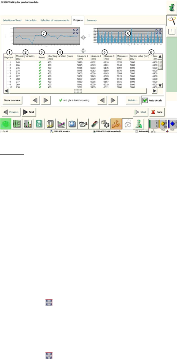
After completion of the measurement, the following results appear in the "Progress" menu:
Figure 22: Cover switching ring mounting result
Legend:
1. Segment measured
2. Calculated Mounting variation value in µm
This value describes the eccentricity (rotation) of the cover switching ring to the central axis
of the segment.
This value is calculated by finding the difference between the lowest and highest analog
voltage value for "Measure1"-"Measure4".
3. Results display (OK green tick / NOK red X)
4. This is the permissible threshold for eccentricity (rotation) of the cover switching ring. The
Mounting variation (2) value and the result (3) refer to this threshold.
5. Measure1 – Measure4 provide the analog voltage values for the light barrier measurement
and show the distance between the Z-down light barrier and the edge of the cover switching
ring at 0°, 90°, 180° and 270°.
6. The Sensor value (min / max) in µm gives the plausible permissible threshold values for
"Measure1" – "Measure4".
7. This diagram illustrates the Mounting variation values for the segments.
Blue line Mounting deviation in µm for individual segments
Red border Min and max tolerances (in our case 0..400mV)
Use the button to zoom in on the diagram.
8. This diagram illustrates the "Measure1" – "Measure4" values for the segments.
Blue bar one bar each for "Measure1"(0°) – "Measure4" (270°)
If the light barrier works reliably, the bars should ideally be the
same height (100% concentricity) or convex/concave (eccentricity)
Red border Min and max tolerances (in our case 5000..6900mV)
Use the button to zoom in on the diagram.
4.5.3 Explanation of Measurement Results Using Results PDF
These results can be seen if you scroll down the "Summary" menu or generate a results PDF!
SIPLACE Head Verification
User Manual Edition 01/2015
36
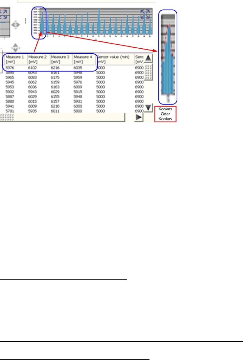
Figure 23: Results PDF for cover switching ring mounting
The bar chart shows how far the cover switching ring rotates around the center of the segment.
The distance values "Measure1" (0°), "Measure2" (90°), "Measure3" (180°) and "Measure4" (270°)
are shown for each segment in the bar chart.
The values "Measure1" – "Measure4" are shown from left to right.
When the light barrier is functioning correctly and the cover switching ring is intact, the bars in the
chart must always have a convex or concave shape.
If the sequence short-long-short-long or long-short-long-short appears, this either indicates that the
light barrier is defective (due to inconsistent measurements) or that the cover switching ring is broken.
If the bar chart has a concave or convex shape but is still outside the tolerances, this indicates that the
cover switching ring is rotating towards the DP axis.
The reason for this could be incorrect fitting of the cover switching ring on the DP seat, that the DP is
running eccentrically (and is therefore damaged) or that the cover switching ring is damaged.
4.5.4 Meaning of the Results
"Mounting variation" error at all segments:
1. Light barrier Z-down defective
The "Measure1"-"Measure4" values are below the thresholds Replace the light barrier Z-
down and Z drive unit assemblies completely
2. Incorrect position of Z-down light barrier
Readjust the Z-down light barrier
3. Z-motor or linear guide of Z drive defective
"Measure1" – "Measure4" errors at multiple segments (not concave / not convex):
1. Light barrier Z-down faulty may have cable break Replace the Z-down light barrier
"Mounting variation" error at individual segments:
1. The "Mounting variation" (2) value is above the "Mounting variation maximum" threshold (4)
Cover switching ring not seated properly on DP or it has fractures
2. One or more "Measure1" – "Measure4" values are under the minimum "Sensor value"
threshold
Cover switching ring is dirty

SIPLACE Head Verification
User Manual Edition 01/2015
37
4.6 "Air & Vacuum with Head Sensors" Measurement
The following tools are required for these measurements:
CPP: 12x nozzle type 2057 03070280-01 (calibration nozzle)
CP20P: 20x nozzle type 4235 03098748-01 (calibration nozzle)
CP20A: 20x nozzle type 1235 03015222-01 (calibration nozzle)
1x calibration tool CPP 03010565-01 or
1x calibration tool C&P20A/P 03034148-01
4.6.1 Explanation of Measurement – Procedure
This measurement is used to determine the vacuum and air blast properties for the placement head
and its segments.The individual measurement steps are used to pinpoint defective components in a
placement head which are impairing the vacuum at the head and therefore causing placement and
pickup errors. In addition, the air blast values are also examined for the placement head.
Firstly, the open and closed vacuum values are determined for the segment, followed by the holding
circuit values for the individual segments.Each segment then has an air blast applied to it. To examine
the vacuum at the segment precisely, the height reference run position is approached and the vacuum
measured at 0°, 90°, 180° and 270° for each segment.This is the only way to reliably check the
vacuum values across the entire DP area, as the rotary system must be completely sealed over the
full 360°.
The results of these measurements are provide feedback about the following sources of errors:
1. State of segment filter disks
2. State of vacuum air-tightness for segment (rotation through 360°)
3. State of vacuum hoses
4. Functionality of vacuum pump (optional)
5. Sate of holding circuit
6. Leaky vacuum nozzle
Measurement procedure details (Example of CPP):
1. The head moves with the calibration nozzles over the nozzle station and moves the Z axis
downwards with the travel profile TP13 [NOZZLE CHANGER DOWN]. This sequence presses
the nozzles firmly against the nozzle seat of the segment again, to achieve the best possible
seal between the nozzle and segment.
2. A clean-up command is then executed at the top position of each segment, to blow any
contaminants off the nozzle and segment and to create the best possible conditions for the
following measurements.
3. The head then moves over the height reference run position on the conveyor side. The Z axis
is moved to the height reference run position in light barrier mode, using the travel profile TP5
[TP5 LIGHT BARRIER].While the Z axis is moving downwards, the vacuum is enabled for this
segment and the Vacuum open [mbar] value is determined.When the Z axis meets the
height reference run position on the conveyor side, the light barrier Z-down is triggered and an
end position signal is emitted.The Vacuum closed [mbar] value is measured there.Both
vacuum values have therefore been determined, with uncovered nozzle (Vacuum open) and
covered nozzle (Vacuum closed).
The Difference "Vacuum closed [mbar] – Vacuum open [mbar]" is used to calculate the
Vacuum delta value in mbar. A certain value must be reached to confirm a reliably
functioning vacuum at the nozzle. The Vacuum delta value in mbar is defined by the type of
nozzle and its cross-section. All thresholds are defined for the calibration nozzle used here.
4. The gantry then moves over the park position and determines the holding circuit values for
each segment. The Holding (nozzle open) [mbar] value determined describes the vacuum
present at an uncovered nozzle, while it is being rotated from the pickup to the placement
cycle (holding circuit). This value should verify the holding force at the nozzle during the
rotation of the star from the pickup to the placement position.
The Open dev. [mbar] value also determined here can not be explained further.