00190585-04.pdf - 第37页
1 Retrofitting Instructions for Coplanarity Option SIPLACE 80 F4/(F4-6)/F5 1.1 Overview of Retrofitting Edition 05/99 1 - 1 1 Retrofitting Instructions Coplanarity Option on SIPLACE 80 F4/(F4-6)/F5 1.1 Overvie w of Retro…
SIPLACE 80 F4/(F4-6)/F5 1 Retrofitting Instructions for Coplanarity Option
Edition 05/99
i - ii
Figures
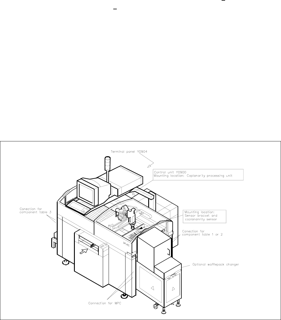
Fig. 1.1.1 Overview of the Machine 80 F4/(F4-6)/F5 (with Optional WPC) and
Mounting Location of the Coplanarity Option . . . . . . . . . . . . . . . . . . . . . . . . . . . . . . . . .1
Fig. 1.2.1 Laser Warning Plates on the Coplanarity Sensor . . . . . . . . . . . . . . . . . . . . . . . . . . . . . .3
Fig. 1.5.1 Cable: Coplanarity Option - Terminal Panel, Item No. 00336795-02
(Sensor -> Front of Control Unit) . . . . . . . . . . . . . . . . . . . . . . . . . . . . . . . . . . . . . . . . . .6
Fig. 1.5.2 Sensor Cable: Coplanarity Option, Item No. 00336793-01
(Sensor -> Front of Control Unit) . . . . . . . . . . . . . . . . . . . . . . . . . . . . . . . . . . . . . . . . . .7
Fig. 1.5.3 Cable: Coplanarity Option - Machine Controller, Item No. 00336796-01
(Control Unit -> Control Unit) . . . . . . . . . . . . . . . . . . . . . . . . . . . . . . . . . . . . . . . . . . . . .8
Fig. 1.5.4 Test Connector: Coplanarity Option, Item No. 00337304-01 . . . . . . . . . . . . . . . . . . . . .8
Fig. 1.5.5 Control Unit: Connector X98 and Cable "Coplanarity Option"
(X98 -> Power Supply Unit (Item No. 00342894-01). . . . . . . . . . . . . . . . . . . . . . . . . . . 9
Fig. 1.5.6 Control Unit: Installing the "Coplanarity Option
Processing Unit " including the Cable . . . . . . . . . . . . . . . . . . . . . . . . . . . . . . . . . . . . . .10
Fig. 1.6.1 Installation of the Coplanarity Sensors (Laser) . . . . . . . . . . . . . . . . . . . . . . . . . . . . . . .15
Fig. 1.8.1 Menu Structure “Software Options” (Station Computer) . . . . . . . . . . . . . . . . . . . . . . . 26
Fig. 1.8.2 Monitor Image, Order of Scanning of Lead Rows . . . . . . . . . . . . . . . . . . . . . . . . . . . . . 28
1 Retrofitting Instructions for Coplanarity Option SIPLACE 80 F4/(F4-6)/F5
1.1 Overview of Retrofitting Edition 05/99
1 - 1
1 Retrofitting Instructions Coplanarity
Option on SIPLACE 80 F4/(F4-6)/F5
1.1 Overview of Retrofitting
The new model of the “Coplanarity” option can be retrofitted on SIPLACE F4 with SW > V 403.04 and on
SIPLACE F
5 (F4-6) with software version > 404.01.
With no further protective measures, the
laser radiation of the new coplanarity sensor is in accordance with
Laser Class
2.
When protective measures are taken, i.e., when the laser is properly installed and the machine is closed, the
laser is in accordance with Laser Class
1 (see Safety Instructions in Section 1.2). Aside from the existing
identifying markings on the coplanarity sensor itself (see Section 1.2), no additional warning signs are
required.
Make certain that the
customer will have a 2nd strong person available throughout the retrofitting process
to
assemble and disassemble the component table and the cutter (see Section 1.2).
The flip-chip and IC camera
remain mounted during the retrofitting. A recalibration of these cameras is there-
fore not necessary. In the event the earlier model of the coplanarity option had a defect, the new model must
be installed. During this process, the old
coplanarity laser module including bracket and coplanarity assembly
(in the control unit) is removed. The current “old” sensor cable is run back inside the machine base such that
it is short-circuit-proof. The cable for the +5 V power supply is not altered (see Section 1.6.1).
Fig. 1.1.1 Overview of the Machine 80 F4/(F4-6)/F5 (with Optional WPC) and Mounting Location of the Coplanarity Option

SIPLACE 80 F4/F5 1 Retrofitting Instructions for Coplanarity Option
Edition 05/99 1.2 Safety Instructions
1 - 2
1.2 Safety Instructions
DANGER O O O
The machines in the SIPLACE family are powered with 3 x 400 V +/- 10%, 50/60 Hz mains voltage.
Portions of the system therefore carry dangerous voltages. Some assemblies inside the machine base do so
even when the main switch is off. Improper handling of the machine or contact with portions thereof which
are live may result in
death or serious bodily injury.
The strict safety standards in DIN EN 69204 must be observed during all work inside the machine base.
See also Chapter 1 of the SIPLACE Service Manual (from June 1998 on).
Only Siemens service engineers are permitted to carry out this retrofitting.
Before beginning the retrofitting, turn the master switch off and pull out the mains plug. In addition, in order to
disassemble and assemble the (“old” or “pneumatic”) cutting tool, the
compressed air feed at the main valve
of the compressed air unit in the machine base must be shut off and air must be bled from the compressed
lines by actuating the vent valve.
Safeguard the machine to prevent it from being reactivated without authority.
As part of the retrofitting, the right-hand component table and the cutter must by dismantled. Therefore make
certain that the
customer will have a 2nd strong person available for the duration of the retrofitting in order
to assemble and disassemble the component table and the cutter.
Depending on the version of the SIPLACE 80 F4 which is to undergo retrofitting, either the “old” cutting tool
(with rotating cutter) or the “pneumatic cutting tool” (with stationary and movable cutting strip) is installed in it.
There is
a high risk of injury from the blades of the cutting tool.
For this reason, you should follow all
SAFETY INSTRUCTIONS in the DANGER text of the pertinent
SIPLACE service manual, Section “Cutting Tool ...”, when installing or removing the cutting tool.
Install/remove it
exactly as specified in the above-mentioned Section.
In particular, comply with those for the “Pneumatic Cutting Tool”.
Never put your hand into the cutting tool from below or into the empty-tape duct from above.
When installing or removing this cutting tool, grasp it
only from above, i.e., the outside left and right, because
when disassembled the
blade is exposed (unprotected) at the bottom.
Never set the disassembled pneumatic cutting tool on your body, for example (e.g., on your knees or
thighs) and
never put your feet under the cutting tool.
If you were to do so, you would injury yourself severely or at least damage your clothes.
Make certain, that
no one can injury themselves on the disassembled cutting tool which you have placed
next to the machine. The best procedure is to put it in an appropriate package (container) right away.
SIPLACE 80 F4 with protective hoods on the component table in the form of
dagger boards:
Removing a dagger board has the same effect as opening a sliding protective hood.
The protective function therefore exists.
SIPLACE 80 F4 / F5 with
swinging doors on the component table:
If a swinging door is not closed, it is mechanically impossible to close the hoods. The protective function
therefore exists.