00190585-04.pdf - 第51页
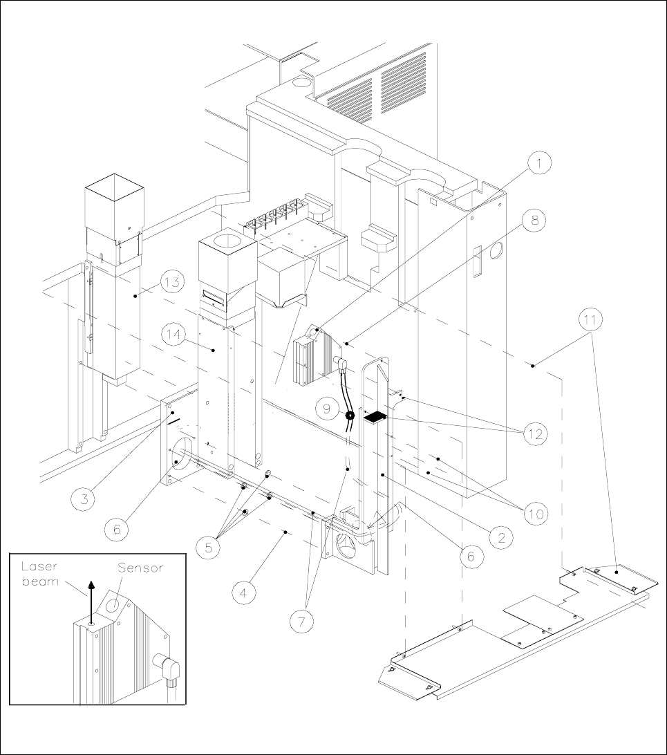
1 Retrofitting Instructions for Coplanarity Option SIPLACE 80 F4/(F4-6)/F5 1.6 Mechanical and Electrical Installation Edition 05/99 1 - 15 Fig. 1.6.1 Installation of the Coplanarity Sensor (Laser)

SIPLACE 80 F4/F5 1 Retrofitting Instructions for Coplanarity Option
Edition 05/99 1.6 Mechanical and Electrical Installation
1 - 14
● Install the new coplanarity sensor (laser) on the new sensor bracket (three M4 x 8 socket hex screws:
see Fig. 1.6.1 -> 8). ->
NOTE
Two cable clips must be used to attach the sensor cable to the sensor bracket on the side facing the
IC camera. This ensures that the cable will not be damaged due to the dust cover.
● Use the cable clips to fasten the sensor cable to the sensor bracket on the side facing the IC camera (see
Fig. 1.6.1 -> 9 and 10: two washers, two M4 x socket head cap screws).
● Afterwards, mount the sensor bracket on the optional carrier (four M6 x 20 screws, see Fig. 1.6.1 -> 4).
CAUTION O
In the case of SIPLACE machines with
dual conveyor (left-hand or right-hand conveyor side = stationary),
two distance washers 1 mm thick each must be placed between the optional carrier and the sensor
bracket per fastening screw (see Fig. 1.6.1 -> 5, Item No. see Section 1.4).
● Connect the existing video and the ribbon cable (= illumination control) back to the flip-chip camera.
● Re-install the cover for the flip-chip camera.
● All cables are in position and connected now.
● Using a bubble level and a metal square, level the coplanarity sensor on the left-hand perpendicular outer
edge of the sensor housing such that it is
exactly at a 90 degree angle to the IC head.
-> NEW: The screws for fastenting of the sensor ar not to
apply with Loctite !
Key to Fig. 1.6.1 (figure to your right):
1) Coplanarity sensor (laser) 2) Sensor bracket
3) Optional carrier for nozzle changer / flip-chip camera 4) Fasteners for sensor bracket
/ coplanarity sensor (remains mounted) Four M 6 x 20 socket-head cap screw
5) 8 ea. distance washers 1 mm thick 6) Opening to run lines for coplanarity sensor
(two washers each of screw) and flip-chip camera
Only in case of dual conveyor,
inserted between bracket and optional carrier !
7) "Sensor cable coplanarity" 8) Fasteners for the sensor (laser)
three M 4 x
8 socket-head cap screws
9) 2 cable clips D = 6 mm 10) Fasteners for cable clips
two washers 4.3 DIN 125-A
two M 4 x 8 socket-head cap screws
11) Metal dust cover over the conveyor trench 12) Contact surfaces for dust cover
Item No. 00343700-01,
Fastening: 3 or 4 ea 4,3 DIN 9021 washers
3 or 4 ea M 4 x 10 socket-head cap screws
13) IC camera (remains mounted) 14) Flip-chip camera (remains mounted)
1 Retrofitting Instructions for Coplanarity Option SIPLACE 80 F4/(F4-6)/F5
1.6 Mechanical and Electrical Installation Edition 05/99
1 - 15
Fig. 1.6.1 Installation of the Coplanarity Sensor (Laser)

SIPLACE 80 F4/F5 1 Retrofitting Instructions for Coplanarity Option
Edition 05/99 1.6 Mechanical and Electrical Installation
1 - 16
1.6.3.2 Conveyor Trench: Adapt and Install New Dust Cover
● Adapt the new cover for the conveyor trench (see Fig. 1.6.1 -> 11) as follows:
Keeping in mind, the options installed, assemble the individual components of the metal dust cover in such
a manner as to ensure that as much of the unused area of the conveyor trench as possible is covered.
-> The new cover is not installed until the last step in “Final Steps”
(see Fig. 1.6.1).
1.6.3.3 Installing the Control Unit: "Coplanarity Processing Unit" (possibly includ-
ing Connector X98), Running and Connecting the Cable at the Control Unit
NOTE
SIPLACE machines with the
following version of control unit are already pre-equipped for the installation
of the
new model of the coplanarity option (version identification: see Fig. 1.5.5):
- Version of control unit
F4: > 00324340-07
- Version of control unit
F4-6: > 00331294-03
- Version of control unit
F5: > 00341851-03
Depending on the version of the control unit involved (see label on the back of the unit Fig. 1.5.5), all
you have to do is slide in the coplanarity processing unit from the retrofitting kit (see Fig. 1.5.6) and make the
plug-in connections on the front of the control unit.
From this version on,
all of the wires running from connector X98 on the back of the control unit to the terminal
panel and from there to the power pack (cable coplanarity, see Fig. 1.5.5), have already been installed.
Proceed as follows for the control unit which is an
earlier model than specified above.
Remove the front panel on the left-hand side next to the ICOS.
● Insert the front subpanel with the premounted plastic nipples (see Fig. 1.5.6 -> 1) on the left-hand side in
the top row, at the slot. Fasten the panel with the two M 2.5 x 11 collar screws (for Item No. see “Retrofit-
ting Kit”, Section 1.4).
● Install the two guide rails and the 2 contact springs each (see Fig. 1.5.6 -> 2 and Fig. 1.5.5) the top of
the control unit (Item No.: see Section 1.4).
● Mount the 15-pin X98 connector (Item No.: see Section 1.4) on the back of the cX98 unit:
● Starting from the front of the control unit and move the connector X98 to the back of control unit (see
Fig. 1.5.5).
● From the inside of the control unit, screw the connector tight to the top and bottom of the back cleats
(two M 2.5 x 6 screws, self-forming, Item No.: see “Retrofitting Kit”, Section 1.4).
NOTE: The ICOS of the earlier control units may also be located in the bottom row of plug-in slots.
● Now run the cable "coplanarity" and wire it (connector X98 -> power pack) as described in Section 1.6.3.4.
● Dismantle the bottom 2 connectors of the ICOS (see Fig. 1.5.6 -> 9), so that you can push in the coplanar-
ity processing unit.