00190585-04.pdf - 第46页
SIPLACE 80 F4/F5 1 Retrof itting Instructions for Coplanarity Option Edition 05/99 1.5 Circuit Diagrams including Views for Control Unit 1 - 10 Fig. 1.5.6 Control Unit: Installing the "Coplanarity Processing Unit &q…
1 Retrofitting Instructions for Coplanarity Option SIPLACE 80 F4/(F4-6)/F5
1.5 Circuit Diagrams including Views for Control Unit Edition 05/99
1 - 9
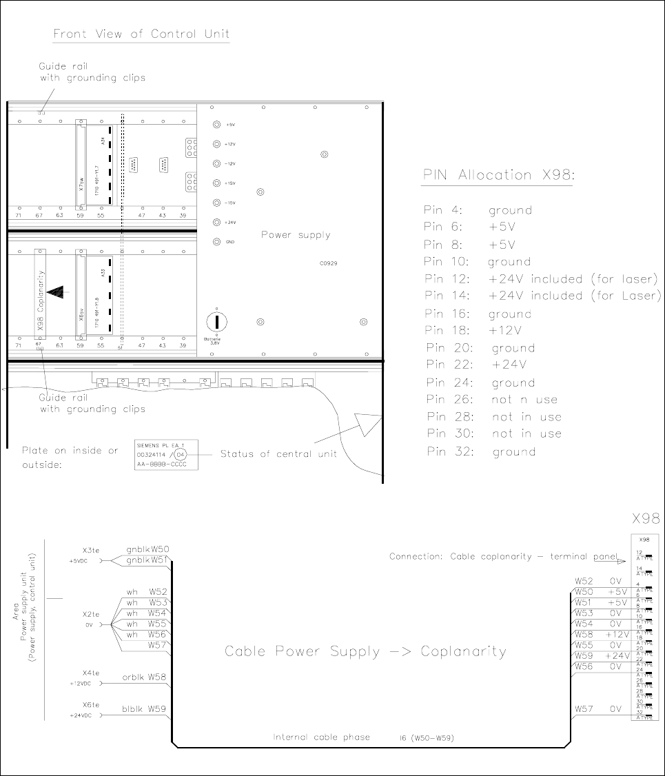
Fig. 1.5.5 Control Unit: Connector X98 and Cable "Coplanarity" from X98 -> Power Supply Unit (Item No. 00342894-01 )
SIPLACE 80 F4/F5 1 Retrofitting Instructions for Coplanarity Option
Edition 05/99 1.5 Circuit Diagrams including Views for Control Unit
1 - 10
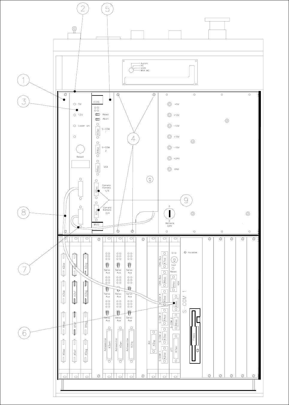
Fig. 1.5.6 Control Unit: Installing the "Coplanarity Processing Unit " including the Cables

1 Retrofitting Instructions for Coplanarity Option SIPLACE 80 F4/(F4-6)/F5
1.6 Mechanical and Electrical Installation Edition 05/99
1 - 11
Key for Fig. 1.5.6 (to your left):
1) Front subpanel, 2) 2 guide rails and 2 contact springs
Fasteners: 2 collar screws, slotted M2.5 x 11 per rail (see Fig. 1.5.5)
3) Control unit : coplanarity processing unit and 4) Fasteners for cover plate
15-pin connector on back of control unit (see Fig. 1.5.5) 4 Torx screws)
5) ICOS (on older control units the ICOS may also 6) Machine controller, COM 1
be located in the bottom row of plug-in slots (V 24 interface)
7) Sensor cable coplanarity 8) Cable: Coplanarity - machine
controller
9) These 2 connectors project over on the left
and must therefore be dismantled
before
installing the coplanarity processing unit.
1.6 Mechanical and Electrical Installation
DANGER O O O
Turn the machine off and pull out the mains plug to the machine.
Comply with
all of the safety instructions in Section 1.2 !
Observe the sequence of the steps in the job.
No bridging of safety equipment is to be performed.
Operating the laser (sensor) outside the machine is not permitted.
1.6.1 Information about the Initial Situation at the Machine
NOTE
SIPLACE machines with the
following version of control unit are already pre-equipped for the installation
of the
new model of the coplanarity (version identification: see Fig. 1.5.5):
- Version of control unit
F4: > 00324340-07
- Version of control unit
F4-6: > 00331294-03
- Version of control unit F5: > 00341851-03
Different initial situations may exist when retrofitting the
new model of the coplanarity option.
- 1st Situation
Machine with a control unit which is an
earlier model than specified above and the earlier model of the
coplanarity option is installed.
This means:
- The old cable running through the inside of the machine base to the laser must be run back inside the