00193888-0402_AI_LBO_HFXD3_DE+EN.pdf - 第47页
Long board 2 Assembly instructions: Long board opt ion - SIPLACE HF-series / X-series / D3 02/2007 Edition 47 2.9 Function check : S tar t the SITEST program. : Check by adjusting the conveyor wid th whether the actuator…
2 Assembly instructions: Long board option - SIPLACE HF-series / X-series / D3 Long board
02/2007 Edition
46
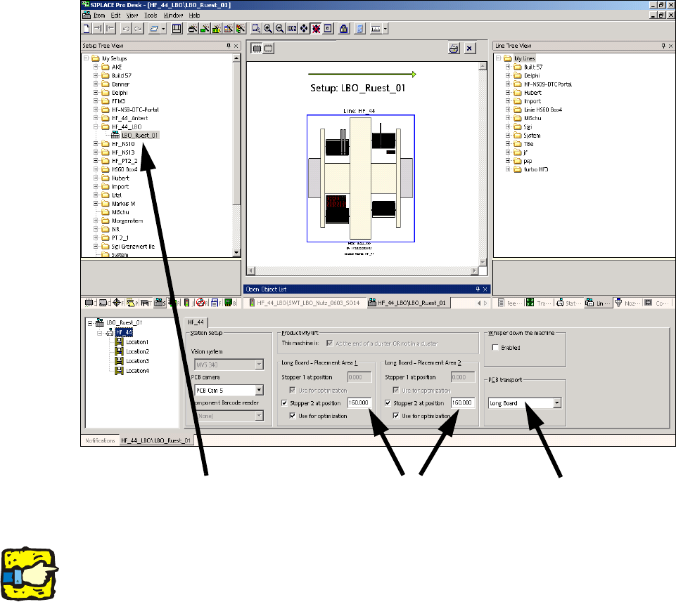
2.8.2 Set-up
: Select a set-up (see screenshot).
: For the PCB conveyor, select "Long board" and enter the value 160,000 under "Stopper 2 at
position" for both processing areas.
2
2
2
The stopper position is not included in the optimization unless the "Use for optimization" box is
checked. 2
2
2
2
2
2
2
Select the set-up
Enter 160.000
Select Long board
Long board 2 Assembly instructions: Long board option - SIPLACE HF-series / X-series / D3
02/2007 Edition
47
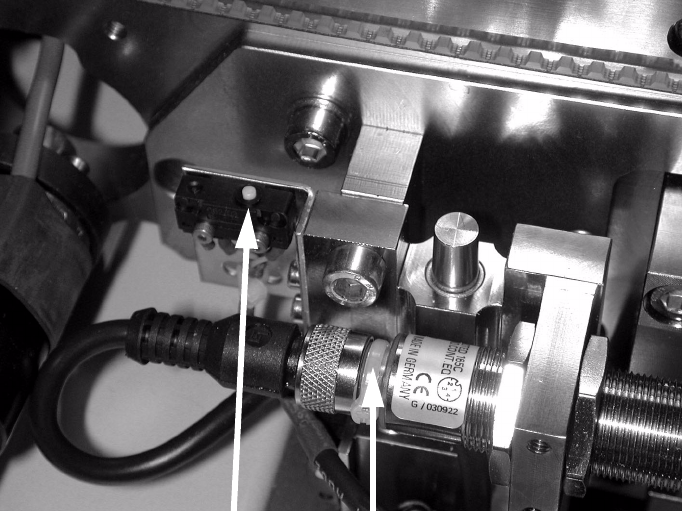
2.9 Function check
: Start the SITEST program.
: Check by adjusting the conveyor width whether the actuators reliably actuate the switches on
the units.
If this is not the case, readjust the affected actuators or units.
2
Teaching the sonar sensor 2
: Place a PCB on the conveyor.
: Push the PCB towards the processing area so that it is over the sensor.
: Hold down the button until the LED flashes (see photograph below).
When teaching mode starts, the LED lights up constantly while the PCB remains in position.
2
2
: Remove the PCB from the conveyor and place it sideways across the conveyor side walls
above the sensor.
The LED must not light up; the LED must only light up if there is a PCB on the conveyor.
2
Button
LED
2 Assembly instructions: Long board option - SIPLACE HF-series / X-series / D3 Long board
02/2007 Edition
48
2.10 Diagrams
2
Fig. 2.10 - 1 Dimensions, connector designation, labeling
2
Dimension / connector designation / labeling
1
2
4
1
2
4
Jumper length
40mm.
gn
bn
b
n
g
n
1
2
4
Teach-in
sonar sensor
Connector 2, sonar sensor
Connector 1
wh
bu
bn
bk
P24
GND
Sensor
Limit switch
Lw4
Lw1
wh
ye
Limit switch
Wdith adjustment
L2w1
ye
wh
bn
gn
L
a
b
e
l s
tu
c
k
o
v
e
r
w
1
,
w
2
, w
3
, w
4
w1
w2
L3w1
L4w1
40
15
Connecotr 1
casing
S
o
l d
e
r
e
d
c
o
n
n
e
c
ti o
n
s
h
r
i n
k
-
fi tte
d
w3
Connector 3, valve
Lw3
bk/rd
bk
1
2
3
4
5
6
7
8
9
10
Connector 2
cylinder switch
w4
bn
gn
wh
bn
gn
wh
GND
P24
Coding
Coding
Cyl. switch
Valve
Lw2
Heat-shrinkable
sleeve
L1w4
1
2
3
11
GND
bn
bn
Limit switch
Wdith adjustment