ET8383-說明書(英文).pdf - 第16页
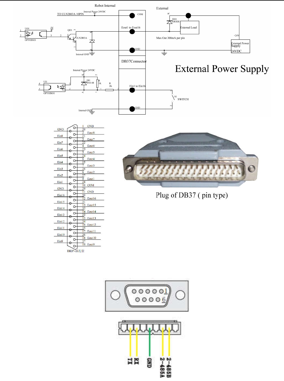
12 3 .4 Instruction abo ut DB9 socket (op tion port) Connection of DB37 plug
11
NO.
De
finition of
DB37 pins
Corresponding I/O
interface of DB37
NO.
Definition
of DB37
pins
Corresponding I/O
interface of DB37
1 G
ND P01 20 GND P20
2 Eout8 P02 21 Ein8 P21
3 Eout7 P03 22 Ein7 P22
4 Eout6 P04 23 Ein6 P23
5 Eout5 P05 24 Ein5 P24
6 Eout4 P06 25 Ein4 P25
7 Eout3 P07 26 Ein3 P26
8 Eout2 P08 27 Ein2 P27
9 Eout1 P09 28 Ein1 P28
10 COM P10 29 G
ND P29
11 G
ND P11 30 Ein16 P30
12 Eout16 P12 31 Ein15 P31
13 Eout15 P13 32 Ein14 P32
14 Eout14 P14 33 Ein13 P33
15 Eout13 P15 34 Ein12 P34
16 Eout12 P16 35 Ein11 P35
17 Eout11 P17 36 Ein10 P36
18 Eout10 P18 37 Ein9 P37
19 Eout9 P19
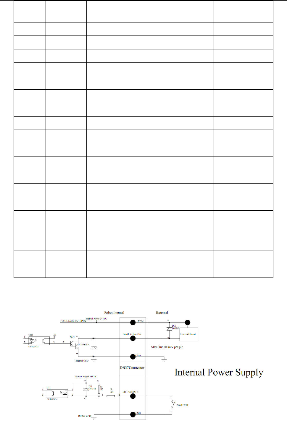
3.3.2 Circuit Instruction of DB37
12
3
.4 Instruction about DB9 socket (option port)
Connection of DB37 plug
13
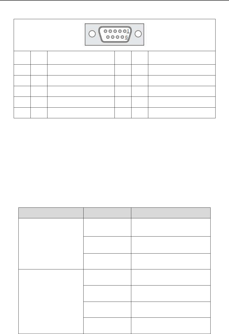
3.4.1 Pins Instruction of DB9
It
em
Pins
Functi
on Item
Pins
Functi
on
1 9P-1
No connection 6 9P-6 No connection
2
9
P-2
TX(Transmitter signal )
7 9P-7
2-485A
3
9P-3
RX(Receiver signal)
8 9P-8
2-485B
4
9
P-4
No connection
9 9P-9
No connection
5
9
P-5
GND(power supply “0V”)
3.5 Instruction of Input & Output
The following input interfaces and output interfaces are corresponding to the signal pins which are defined as
“Min, Mout, Ein, Eout” at the above socket. Also, it is corresponding to the interface at the “IO Test
”
dis
playing window.
After setting, it can test the function of IO interface at the “IO Test” displaying window.
The interfaces in following table can be set at the “Input Config” or “Output Config” of “System Config 2”
of teaching pendant. It can define the special function for the following input & output interfaces which are
corresponding to the above sockets.
Main board port defined functions are listed in following table:
Board Port Function
Expansi
on input port
Ein12 Block material alarm signal
Ein13 L
ack material alarm signal
Ein14 Tem
perature alarm signal
Mai
n input port
Min1 Reset key signal
Mi
n2 Emergency stop key signal
Mi
n3 Safety signal
Mi
n4 Start/pause key signal