ET8383-說明書(英文).pdf - 第22页
18 Nam ely , “Eout8+ 1” is the output interface “Eou09”. “Eout8+ 2” is the ou tput i nterface “Eo u10”. “Eout8+ 3” is the o utput interface “Eou1 1”, etc. 3.5.2 IO Function Instruction Input si gnal functi on Functio n I…

17
Eout3
-
-, Nozzle 1, Nozzle 2, Nozzle 3, Nozzle 4
Eout4
-
-, Nozzle 1, Nozzle 2, Nozzle 3, Nozzle 4
Eout5
-
-, Nozzle 1, Nozzle 2, Nozzle 3, Nozzle 4
Eout6
-
-, Nozzle 1, Nozzle 2, Nozzle 3, Nozzle 4
Eout7
-
-, Nozzle 1, Nozzle 2, Nozzle 3, Nozzle 4
Eout8
-
-, Nozzle 1, Nozzle 2, Nozzle 3, Nozzle 4
Eout9
-
-, Ready Flag, Alarm Flag, Working Flag, Work End Flag, Cylinder,
Clean Output, Pause Output, Left LED, Right LED, Emer Output,
Eout10
-
-, Ready Flag, Alarm Flag, Working Flag, Work End Flag, Cylinder,
Clean Output, Pause Output, Left LED, Right LED, Emer Output,
Reset Output, EnNozzleAdj
Eout1
1
-
-, Ready Flag, Alarm Flag, Working Flag, Work End Flag, Cylinder,
Clean Output, Pause Output, Left LED, Right LED, Emer Output,
Reset Output, EnNozzleAdj
Eout12
-
-, Ready Flag, Alarm Flag, Working Flag, Work End Flag, Cylinder,
Clean Output, Pause Output, Left LED, Right LED, Emer Output,
Reset Output, EnNozzleAdj
Eout13
-
-, Ready Flag, Alarm Flag, Working Flag, Work End Flag, Cylinder,
Clean Output, Pause Output, Left LED, Right LED, Emer Output,
Reset Output, EnNozzleAdj
Eout14
-
-, Ready Flag, Alarm Flag, Working Flag, Work End Flag, Cylinder,
Clean Output, Pause Output, Left LED, Right LED, Emer Output,
Reset Output, EnNozzleAdj
Eout15
-
-, Ready Flag, Alarm Flag, Working Flag, Work End Flag, Cylinder,
Clean Output, Pause Output, Left LED, Right LED, Emer Output,
Reset Output, EnNozzleAdj
Eout16
-
-, Ready Flag, Alarm Flag, Working Flag, Work End Flag, Cylinder,
Clean Output, Pause Output, Left LED, Right LED, Emer Output,
Reset Output, EnNozzleAdj
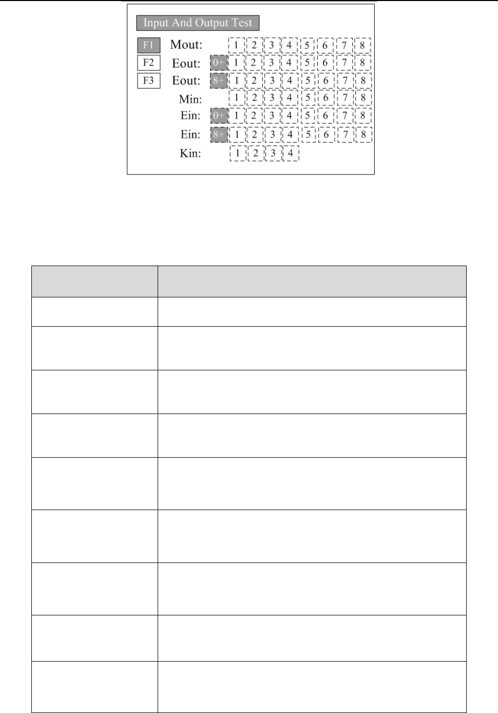
3.I
n the teaching pendant, “Eout09~Eout16” are corresponding to the “Eout8+ (0~8)” at the “I
O
T
est” and “Output (point)” displaying window.
18
Nam
ely, “Eout8+ 1” is the output interface “Eou09”. “Eout8+ 2” is the output interface “Eou10”.
“Eout8+ 3” is the output interface “Eou11”, etc.
3.5.2 IO Function Instruction
Input si
gnal function
Functio
n Instruction
-- N/A.
Origi
n BTN
Input the reset signal into the unit by corresponding signal pin, and
the unit will run the reset (ORG) operation.
S
top BTN
Input the stop signal into the unit by corresponding signal pin, and
the unit stops the current operation.
S
tart BTN
Input the start signal into the unit by corresponding signal pin, and
the unit starts to work or pauses the current work.
F
oot BTN
Input the foot switch signal into the unit by corresponding signal pin
and the unit runs the foot switch operation and the function is
similar with the “Start BTN”.
Safe f
lag-1
Input the signal “breakover ground” into the unit by corresponding
signal pin and the unit comes into the testing state (cannot move and
can only be programmed).
Safe f
lag-2
Input the signal “break over ground” into the unit by corresponding
signal pin and the unit comes into the testing state (cannot move and
can only be programmed).
L
ack fault
Input the signal “lack fault” into the unit by corresponding signal pin
and the unit comes into the process, such as stop working, alarming
et
c..
Block f
ault
Input the signal “block fault” into the unit by corresponding signal
pin and the unit comes into the process, such as stop working,
alarming etc..

19
T
emp fault
Input the signal “temp fault” into the unit by corresponding signal
pin and the unit comes into the process, such as stop working,
alarming etc..
T
emp/Feed fault
Input the signal “temp/feed fault” into the unit by corresponding
signal pin and the unit comes into the process, such as stop working,
alarming etc..
Upper CS
Input the signal “cylinder up sensor (in retraction state)” into the
unit by corresponding signal pin and the unit judges the position of
cylinder whether in retraction state.
Nether
CS
Input the signal “cylinder down sensor (in reaching state)” into the
unit by corresponding signal pin and the unit judges the position of
cylinder whether in reaching state.
Adj X-Limit
Adj Y-Limit
Adj Z-Limit
It is effective only for the soldering robot and only when connecting
with “9036 tip calibration device”. “Adj X-Limit” is
corresponding to the “Ein09”. Input the signal by “Ein09” to
calibrate the X-axis of tip. “Adj Y-Limit” is corresponding to the
“Ein10”. Input the signal by “Ein10” to calibrate the Y-axis of tip.
“Adj Z-Limit” is corresponding to the “Ein11”. Input the signal by
“Ein11” to calibrate the Z-axis of tip. (Note: only calibrating X/Y/Z
at the same time, it can calibrate the tip’s position.)
Short
cut
It is corresponding to the shortcut of processing file. The shortcut
can be set in the “File Name” display window of teaching pendant.
It can be used do find the required processing files quickly.
Short
cut1 Min1
Short
cut 2 Min2
Short
cut 3 Min3
Short
cut 4 Min4
Shortcut 5~259
It is corresponding to the “Ein1~Ein8”. Namely, the high & low
electrical level of “Ein1~Ein8” can form 255 (1~255) kinds signal.
The shortcut (5~259) is the sum of the electrical level digit add 4.
P
ressure flag
The condition of air pressure.
Output signal function Function Instruction
-- Not have function.
Nozzle
1
Once the nozzle 1 comes to run the program, the output is in
conducting state, or else not.
Nozzle
2
Once the nozzle 2 comes to run the program, the output is in
conducting state, or else not.