YS12P_YS12F_Mainte_E.pdf - 第126页
A-1 Appendix 1. Specifications 1.1 Air regulator unit T he air regulator for controlling the air pressure to the pneumatic units of the machine is located behind the front lower left panel. Air pressure setting for machi…

A-1
Appendix
1. Specifications
1.1 Air regulator unit
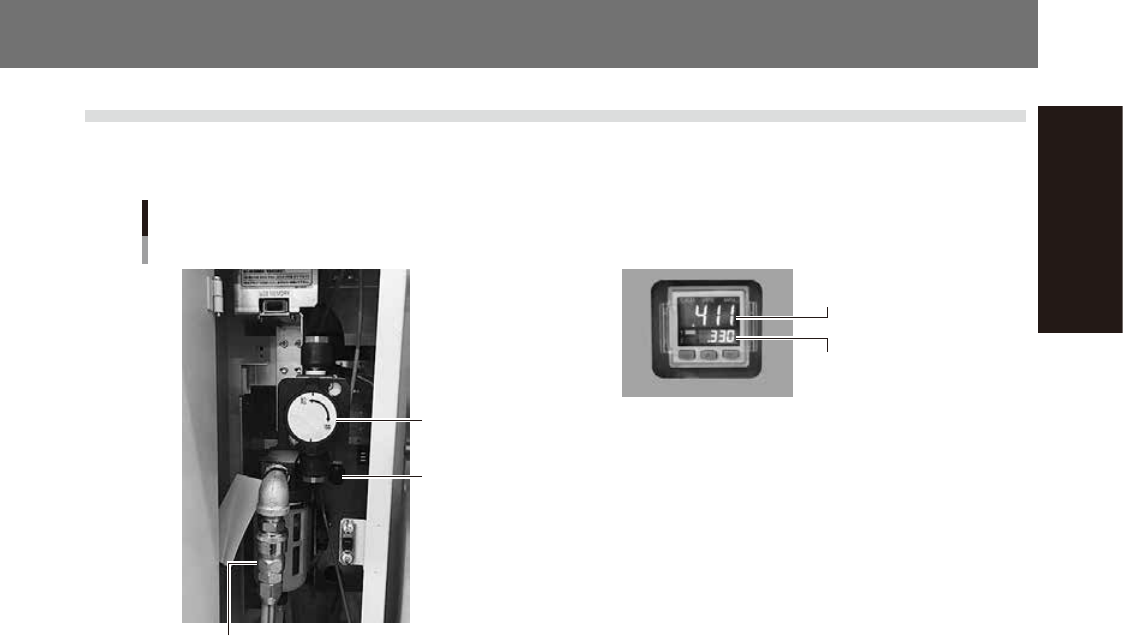
The air regulator for controlling the air pressure to the pneumatic units of the machine is located behind the
front lower left panel.
Air pressure setting
for machine
YS12P
YS12F
Air pressure regulator and pressure gauge
Source air connector
Air pressure regulator
(For machine)
Air supply/exhaust
switch (valve)
Pressure-drop
detection level
53A01-L6-00
n
Supply air pressure
This is the pressure of the source air supplied to the machine. Before setting the air pressure with the air regulator, make
sure that this supply air pressure is in the following optimal range.
YS12P, YS12F : 0.45MPa to 0.70MPa
n
Digital pressure gauge
Shows the supply air pressure (upper reading) and pressure-drop detection level (lower reading). A normal pressure value
is shown in green, and a pressure value lower than the pressure-drop detection level is shown in red.
n
Air pressure setting and pressure-drop detection level
• YS12P, YS12F
Air pressure setting for machine (upper reading) : 0.40MPa to 0.41MPa
Pressure-drop detection level (lower reading) : 0.33MPa
n
Air supply/exhaust switch (valve)
Turning this switch to the right shuts off air supply and exhausts air that remains inside the machine.
n
Source air connector
Prepare an air hose with an inner diameter of at least 8mm having a 40SH socket (Nitto Koki, or equivalent), and connect
it to this connector. Use dry, clean air passed through an air filter.
A-2
Appendix
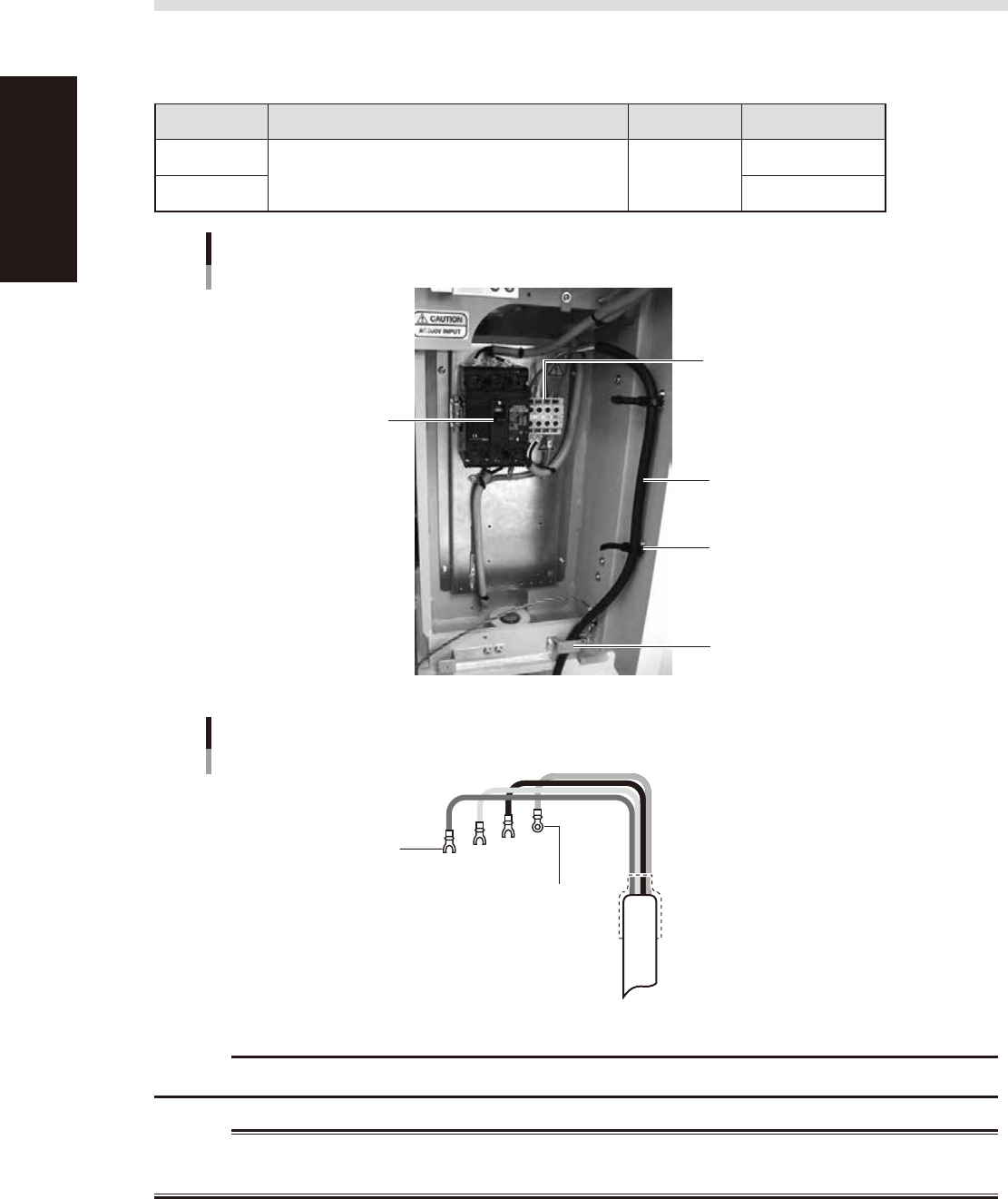
1.2 Power connection terminals
The power connection terminals are located inside the lower right panel on the front of the machine. Connect
the power cable leads as shown below to the L1, L2, L3 and ground terminal (PE) on the power terminal block.
n
Power supply specifications
Model name Power Frequency Power capacity
YS12P
3-phase AC 200/208/220/240/380/400/416V (±10%) 50/60Hz
3.6kVA
YS12F 4.9kKVA
Power connection terminals
Main breaker
Power input terminals
(L1, L2, L3) and ground terminal
Power cable
Secure the clamps at two
positions
Wire through this clamp plate
53A02-L6-00
L1
L2
L3
PE
L=100mm
Power cable example
Fork-tongue crimp terminal
Ring-tongue crimp
terminal
53A03-L&-00
c
CAUTION
Use a power cable whose conductor cross-section area is greater than 3.5mm
2
.
w
WARNING
TO AVOID THE RISK OF ELECTRICAL SHOCK, MAKE SURE THAT THE POWER SOURCE IS OFF BEFORE CONNECTING THE
POWER CABLE. ALSO MAKE SURE THAT THE GROUND CABLE IS SECURELY CONNECTED TO THE MACHINE.