YS12P_YS12F_Mainte_E.pdf - 第77页
3-12 3 Periodic maintenance items 2.2 Inspecting ball screws and guides of each axis Inspect the ball screws and the guides on the X, Y , W , and push-up axes. Checkpoints are listed belo w . An anti grease splatter cove…
3-11
3
Periodic maintenance items
2. Monthly inspection
2.1 Cleaning the nozzle air path
Clean the nozzle air path if a nozzle clogging is found in the daily inspection or every month.
e
1
Remove the nozzle from the head.
1. Press the emergency stop button and
then open the machine safety cover.
2. Remove the nozzle from the head. If the
machine is equipped with the nozzle
station, press the [Nozzle Stn Shutter]
button to open the nozzle station shutter
and remove the nozzle.
2
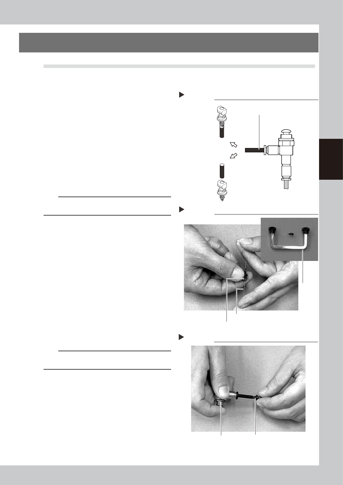
Blow air through the nozzle.
Using an air blow tool, blow air through the
nozzle from the nozzle tip and then from the
other end.
53310-L6-00
n
NOTE
If there are dust deposits in the nozzle, perform steps 3
and 4.
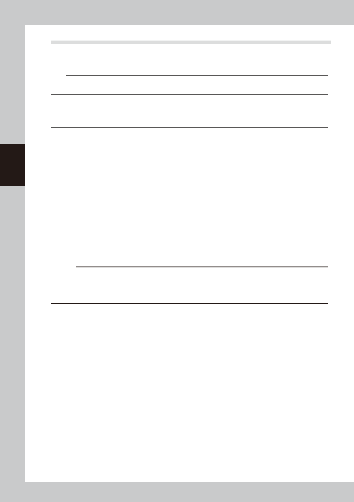
3
Clean the nozzle hole.
Pass the nozzle cleaning wire through the
nozzle hole and clean the nozzle hole. While
holding both ends of the wire with fingers or
using a custom handle (option) shown in the
figure on the right, gently move the nozzle
back and forth.
53311-L6-00
4
Blow air onto the nozzle tip again.
After removing the cleaning wire, blow air
through the nozzle with the air blow tool, just
as in step 2.
53312-L6-00
5
Return the nozzle to its original
head.
n
NOTE
If removed nozzles from the nozzle station, return them
to the nozzle storage positions.
Air blow
Step 2
Air tube (black)
Air blow tool
(option)
Air tube (orange) connected to
air supply port
Insert the
nozzle tip into
the air tube and
blow air.
Blow air from the
nozzle attachment
side.
Cleaning a nozzle
Step 3
Custom
handle
(option)
Nozzle
Nozzle cleaning wire
Air blow
Step 4
NozzleAir blow tool (option)
3-12
3
Periodic maintenance items
2.2 Inspecting ball screws and guides of each axis
Inspect the ball screws and the guides on the X, Y, W, and push-up axes. Checkpoints are listed below.
An anti grease splatter cover is attached to the X and Y axes. Remove these covers when inspecting the ball
screws and guides.
TIP
See "3.1 Cleaning and greasing the X and Y axis" described later on for detaching or attaching the anti grease
splatter cover.
TIP
See "3.1 Cleaning and greasing the X and Y axis", "3.2 Cleaning and greasing the push-up axis (PU axis)" and "5.3
Cleaning and lubricating the W-axis" in this chapter, and "Chapter 5 Lubrication points and schedule" for positions of
ball screws and guides of each axis.
1. Any foreign objects adhering to the ball screws and guides?
Check if any fallen chips have adhered to the ball screws and/or guides.
2. Do the ball screws and guides have the correct amount of grease?
Check if grease has flowed off or splattered in the air failing to adhere. Also check if grease has discolored or hardened.
e
3. Any abnormal sounds from the ball screws?
Press the emergency stop button. Check for any abnormal sounds by pressing the X-axis or Y-axis back and forth
manually.
Countermeasures
1. Ball screws and guides may be damaged when chips and other material bite into them. If chips are adhering, wipe
them off along with the grease or remove with tweezers, etc.
2. Apply grease referring to "3.1 Cleaning and greasing the X and Y axis", "3.2 Cleaning and greasing the push-up axis (PU
axis)" and "5.3 Cleaning and lubricating the W-axis" in this chapter described later on.
3. Contact YAMAHA sales representative when abnormal sounds occur even after trying the countermeasures in the above
steps 1 and 2.
w
WORNING
THIS MACHINE CONTAINS PARTS GENERATING STRONG MAGNETIC FIELDS. GREAT CARE SHOULD BE TAKEN WHEN A PART
OF YOUR BODY IS PUT INSIDE THE MACHINE FOR THE MAINTENANCE WORK. CAUTIONS REGARDING FERROMAGNETIC
FIELDS ARE DESCRIBED IN THE SECTION, “SAFETY INSTRUCTIONS”, AT THE BEGINNING OF THIS DOCUMENT. ALWAYS
THOROUGHLY READ THIS SECTION TO FULLY UNDERSTAND ITS CONTENTS.
3-13
3
Periodic maintenance items
3. Two-month inspection
3.1 Cleaning and greasing the X and Y axis
This section describes how to clean and grease the X and Y axes. See "Chapter 5 Lubrication points and
schedule" for lubrication points and lubrication form. Prepare a grease gun and specified grease (NSL).
c
CAUTION
When handling grease or lubricant, read and follow the precautions in the "Safety instructions" and Section"2.2.2
Lubricating tools and grease" in Chapter 1.
c
CAUTION
If abnormal sound is heard from the X and Y axis ball screws or guides, contact YAMAHA sales representative.
Disassembly and cleaning of the ball screws or guides by the user will void the warranty.
3.1.1 Cleaning and greasing the X and Y axis ball screws
e
1
Prepare for maintenance work.
1. Press the emergency stop button and
then open the machine safety cover.
2. If the machine is equipped with a
carriage, remove the carriage to easily
access to the X axis and Y axis.
2
Remove the anti grease splatter
covers.
Remove the anti grease splatter covers of X,
Y1, and Y2 axes.
X-axis
1. Use a Phillips screwdriver to remove the
screws mounting the left side of the anti
grease splatter cover.
2. Move the head unit all the way to the
left side and remove the screws
mounting the right side of the anti grease
splatter cover.
3. Remove the anti grease splatter cover
by pulling it to the right.
53305-L6-00
TIP
When reattaching the X-axis anti grease splatter cover,
use the reverse order of the above procedure.
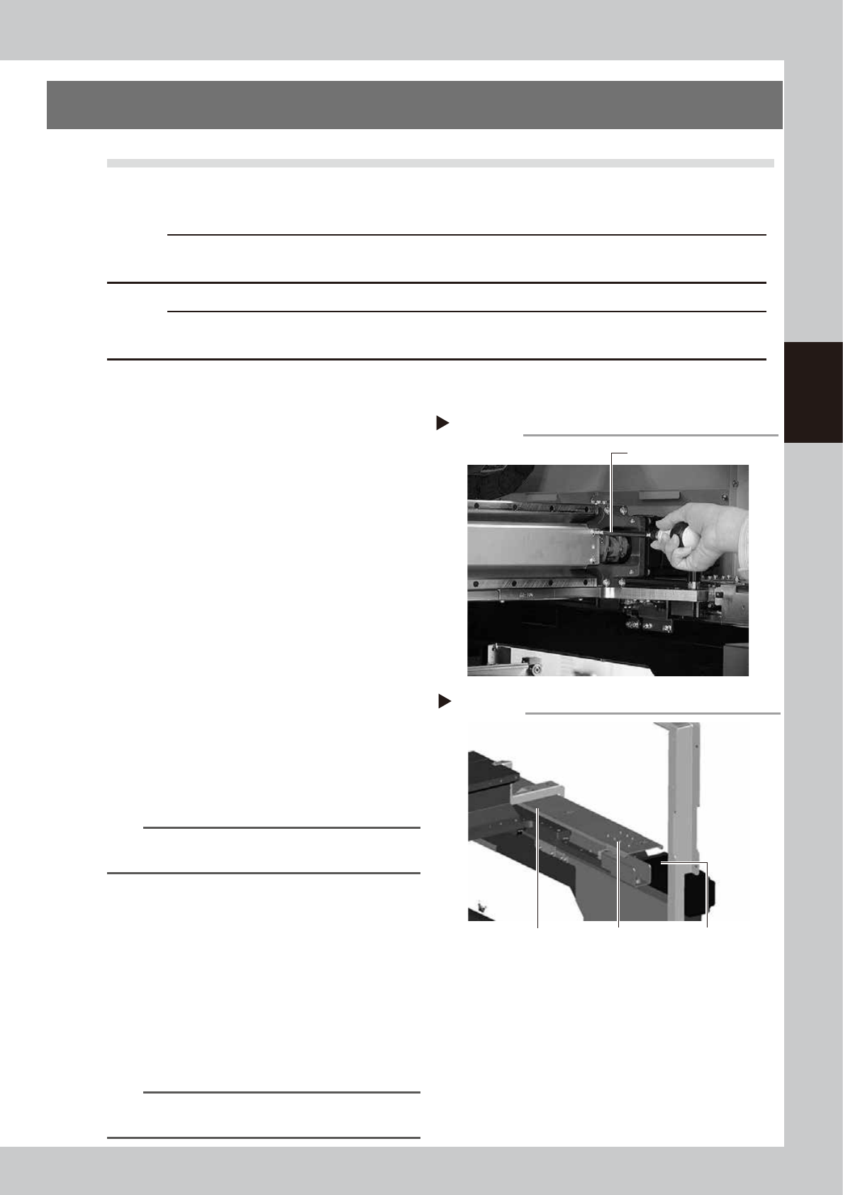
Y1 and Y2 axes
1. Use the hex wrench to remove the screws
mounting the rear side of the anti grease
splatter cover.
2. Move the head unit all the way to the
rear side and remove the screws
mounting the front side of the anti grease
splatter cover.
3. Remove the anti grease splatter cover
by pulling it to the front.
53306-L6-00
TIP
When reattaching the Y-axis anti grease splatter covers,
use the reverse order of the above procedure.
Removing the X-axis grease spattering prevention cover
Step 2
Phillips screwdriver
Y-axis ball screw cover
Step 2
Y-axis ball screw
cover mounting bolt
Y-axis motor
Removing the Y-axis grease spattering prevention cover