YS12P_YS12F_Mainte_E.pdf - 第81页
3-16 3 Periodic maintenance items 3.2 Cleaning and greasing the push-up axis (PU axis) T he push-up axis prevents flexing or warping of the board during clamping. It is important as it prevents depressing of the board du…
3-15
3
Periodic maintenance items
3.1.2 Cleaning and greasing the X, Y and W axes guides
e
1
Prepare for maintenance work.
1. Press the emergency stop button and
then open the machine safety cover.
2. If the machine is equipped with a
carriage, remove the carriage to easily
access to the X axis and Y axis
2
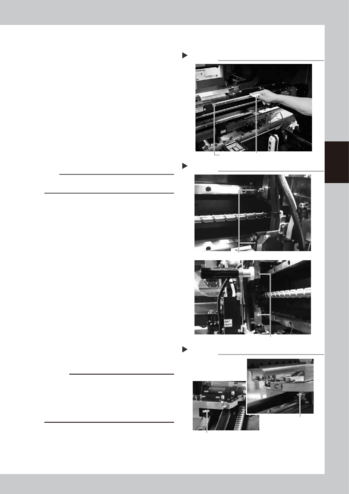
Clean the guides.
1. After moving each axis to the edge,
clean the whole guide with a lint-free
cloth that does not raise dust.
2. Move the axis to the opposite side and
wipe the opposite side guides (X-axis and
Y-axis).
53313-L6-00
n
NOTE
Wipe away thoroughly the old grease in the grooves of
the guide rails.
3
Apply grease to the guides.
1. X-axis
Use the grease gun to apply the
specified grease (NSL) to the X-axis guide
grease nipples.
The grease nipples are located behind
the head unit, 2 each on the right and
left (total of 4 positions). The grease
nipple includes 2 sizes. Attach the
standard or the bent type nozzle to the
grease gun and grease the X-axis guide.
53314-L6-00
2. Y1-axis and Y2-axis
Use the grease gun to apply the
specified grease (NSL) to the Y-axis guide
grease nipples. The grease nipples are
located on the front and back sides of
the slider on each Y-axis guide (total of 4
positions).
Attach the nozzle aligning with the angle
of the grease nipple.
53329-L6-00
c
CAUTION
Align the grease gun nozzle with the angle of the
grease nipple and push the nozzle straight to the nipple
when injecting grease from the bent type grease
nipple. If not aligned, the grease nipple may be
damaged or may come loose and fall off. Carefully
apply the grease.
4
Remove excess grease.
After moving the axis left and right (X-axis)
or back and forth (Y-axis) manually a few
times, wipe away excess grease.
Cleaning the guides
Step 2
Guide rail Wipe with cleaning cloth or paper towel.
Greasing the X-axis guide
Step 3-1
Grease nipple (small)
Grease nipple (large: located on head holder)
Greasing the Y-axis guide
Step 3-2
Grease nipple for
Y-axis guide
Grease nipple for Y-axis guide Total of 4 places
3-16
3
Periodic maintenance items
3.2 Cleaning and greasing the push-up axis (PU axis)
The push-up axis prevents flexing or warping of the board during clamping. It is important as it prevents
depressing of the board during component mounting.
The push-up axis also prevents deviations in the component mounting accuracy due to the board depressing
during component mounting. Periodic cleaning and lubricating the push-up axis is required to ensure it
operates correctly.
c
CAUTION
If trouble occurs with the push-up axis, contact YAMAHA sales representative. Disassembly and cleaning of the
push-up axis by the user will void the warranty.
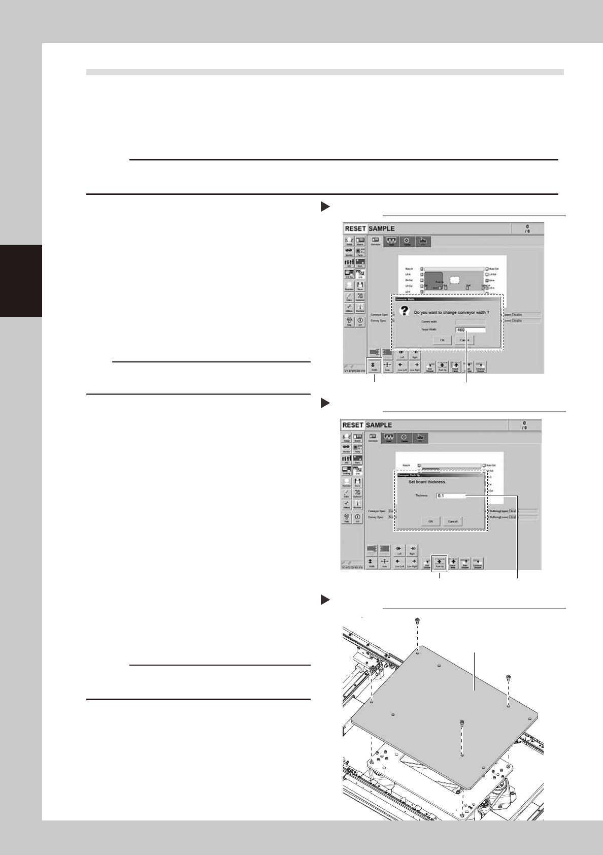
1
Change the conveyor width to its
maximum width.
1. Press the [Conveyor Width] button on the
[Unit] – [Conveyor] screen to display the
“Conveyor Width” screen.
2. Enter the maximum value of the
conveyor width in the “Changed
conveyor width”, press [OK]. The
conveyor is changed to the width that
was just entered.
54310-L6-10
TIP
The maximum conveyor width value is 460 mm or 410
mm in standard specification.
2
Raise the push-up unit.
1. Press the [Push-up] button to display the
“Conveyor Push-up” screen.
2. Enter “0.1 mm” in “Thickness”, and press
the [OK] button. The push-up unit moves
up.
54319-L6-00
e
3
Remove the push-up plate.
1. Press the emergency stop button and
then open the machine safety cover.
2. If the machine is equipped with a
carriage, remove the carriage to easily
access to the push-up axis.
3. Removed the fixed bolts (four locations)
on the push-up plate using the hex
wrench (4) to remove the push-up plate.
53354-L6-00
c
CAUTION
The push-up plate is heavy. Use plenty of caution when
handling.
4
Remove the old grease.
Remove the old grease from the 2 ball
screws and 2 ball guides with lint-free cloth
that does not raise dust.
Changing the conveyor width
Step 1
[width] button Enter the maximum conveyor value
Raise the push-up unit
Step 2
[Push Up] button Enter ”0.1 mm”
Removing the push-up plate
Step3
Push-up plate
3-17
3
Periodic maintenance items
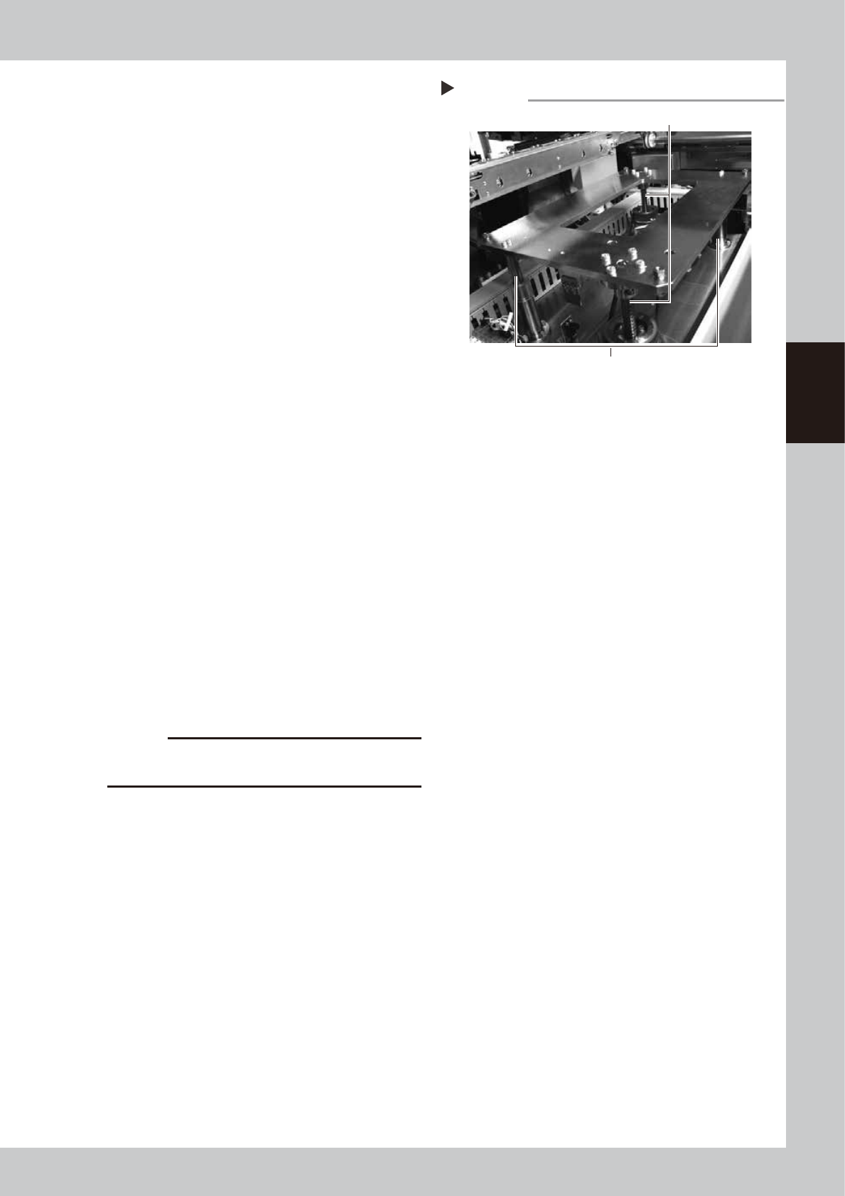
5
Apply the new grease.
Ball screw
Apply as much as 2 cm of specified grease
(NSL) to finger. Rub it evenly into the ball
screw grooves.
Ball guide
Apply as much as 2 cm of specified grease
(NSL) to finger. Coat it evenly on the ball
guides.
53331-L6-00
6
Set the applied grease.
1. Close the machine’s safety cover, and
cancel the emergency stop. In case the
specification has a carrier, set the carrier.
2. Press the [Push-up] button to lower the
push-up unit.
3. Follow the Step 2 procedure to raise the
push-up unit.
4. Repeat Step 2 and 3 several times to set
the grease. After setting the grease,
leave the push-up unit in the up state.
e
7
Wipe away excess grease.
1. Press the emergency stop button, and
open the machine’s safety cover. In case
the specification has a carrier, remove
the carrier.
2. Wipe the excess grease with lint-free
cloth that does not raise dust.
8
Attach the push-up plate to its
original position.
Attach the push-up plate in the reverse
procedure of step 3.
c
CAUTION
The push-up plate is heavy. Use plenty of caution when
handling.
Applying the grease
Step 5
Ball guides (2 places)
Ball screws (2 places)