YS12P_YS12F_Mainte_E.pdf - 第79页
3-14 3 Periodic maintenance items 3 Clean the ball screws. 1. Grasp the carrying handle to move each axis to one end. 2. Wipe away the old grease and dirt from the ball screw with a lint-free cloth that does not raise du…
3-13
3
Periodic maintenance items
3. Two-month inspection
3.1 Cleaning and greasing the X and Y axis
This section describes how to clean and grease the X and Y axes. See "Chapter 5 Lubrication points and
schedule" for lubrication points and lubrication form. Prepare a grease gun and specified grease (NSL).
c
CAUTION
When handling grease or lubricant, read and follow the precautions in the "Safety instructions" and Section"2.2.2
Lubricating tools and grease" in Chapter 1.
c
CAUTION
If abnormal sound is heard from the X and Y axis ball screws or guides, contact YAMAHA sales representative.
Disassembly and cleaning of the ball screws or guides by the user will void the warranty.
3.1.1 Cleaning and greasing the X and Y axis ball screws
e
1
Prepare for maintenance work.
1. Press the emergency stop button and
then open the machine safety cover.
2. If the machine is equipped with a
carriage, remove the carriage to easily
access to the X axis and Y axis.
2
Remove the anti grease splatter
covers.
Remove the anti grease splatter covers of X,
Y1, and Y2 axes.
X-axis
1. Use a Phillips screwdriver to remove the
screws mounting the left side of the anti
grease splatter cover.
2. Move the head unit all the way to the
left side and remove the screws
mounting the right side of the anti grease
splatter cover.
3. Remove the anti grease splatter cover
by pulling it to the right.
53305-L6-00
TIP
When reattaching the X-axis anti grease splatter cover,
use the reverse order of the above procedure.
Y1 and Y2 axes
1. Use the hex wrench to remove the screws
mounting the rear side of the anti grease
splatter cover.
2. Move the head unit all the way to the
rear side and remove the screws
mounting the front side of the anti grease
splatter cover.
3. Remove the anti grease splatter cover
by pulling it to the front.
53306-L6-00
TIP
When reattaching the Y-axis anti grease splatter covers,
use the reverse order of the above procedure.
Removing the X-axis grease spattering prevention cover
Step 2
Phillips screwdriver
Y-axis ball screw cover
Step 2
Y-axis ball screw
cover mounting bolt
Y-axis motor
Removing the Y-axis grease spattering prevention cover
3-14
3
Periodic maintenance items
3
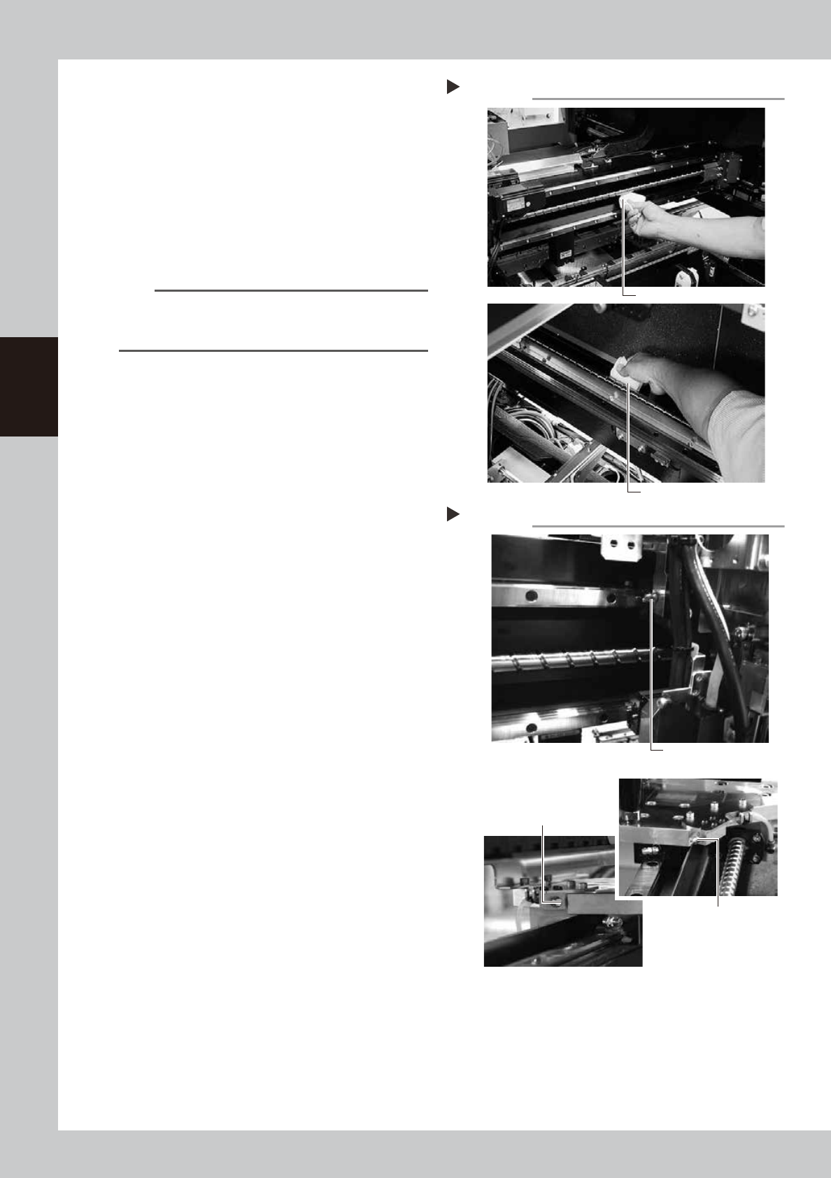
Clean the ball screws.
1. Grasp the carrying handle to move each
axis to one end.
2. Wipe away the old grease and dirt from
the ball screw with a lint-free cloth that
does not raise dust (for clean room use).
3. Move the axes to the opposite end and
wipe the opposite side ball screw clean
(X and Y axes).
53307-L6-10
n
NOTE
Carefully wipe the lead grooves of the ball screws
during the cleaning work. Additionally, make sure that
any dirt is not produced.
4
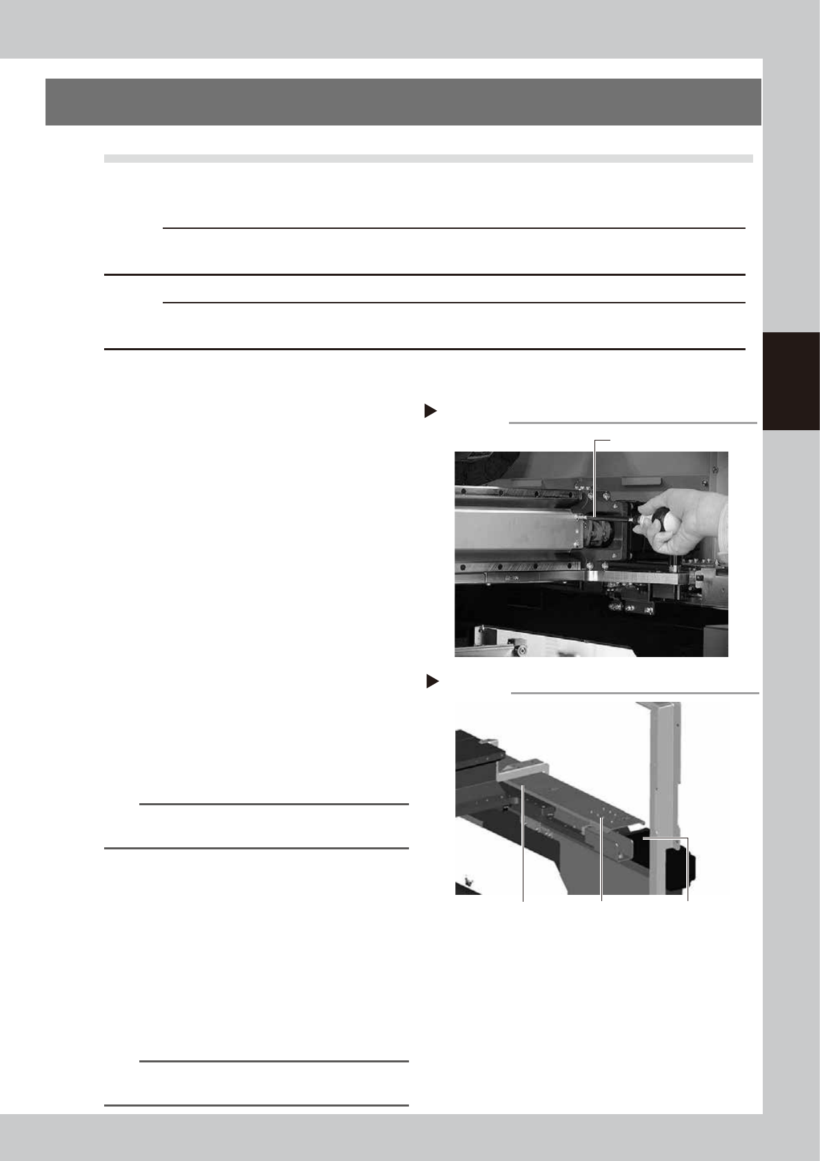
Apply grease to the ball screws.
X-axis
Use the grease gun (with Standard nozzle) to
supply the specified grease (NSL) to the
grease nipples.
Y-axis
Use the grease gun (with Standard nozzle) to
supply the specified grease (NSL) to the
grease nipples.
Move the axis left and right (X-axis) or back
and forth (Y-axis) manually and wipe away
excess grease.
53315-L6-10
5
Reattach the covers.
Reattach the anti grease splatter covers in
the reverse order of the removal procedures.
Cleaning the ball screws
Step 3
Wipe with cleaning cloth, etc.
X-axis
Y-axis
Wipe with cleaning cloth, etc.
Greasing the ball screws
Step 4
Grease nipple for
X-axis ball screw
Grease nipple (right) for
Y-axis ball screw
Grease nipple (left) for
Y-axis ball screw Y-axis
X-axis
Y-axis
3-15
3
Periodic maintenance items
3.1.2 Cleaning and greasing the X, Y and W axes guides
e
1
Prepare for maintenance work.
1. Press the emergency stop button and
then open the machine safety cover.
2. If the machine is equipped with a
carriage, remove the carriage to easily
access to the X axis and Y axis
2
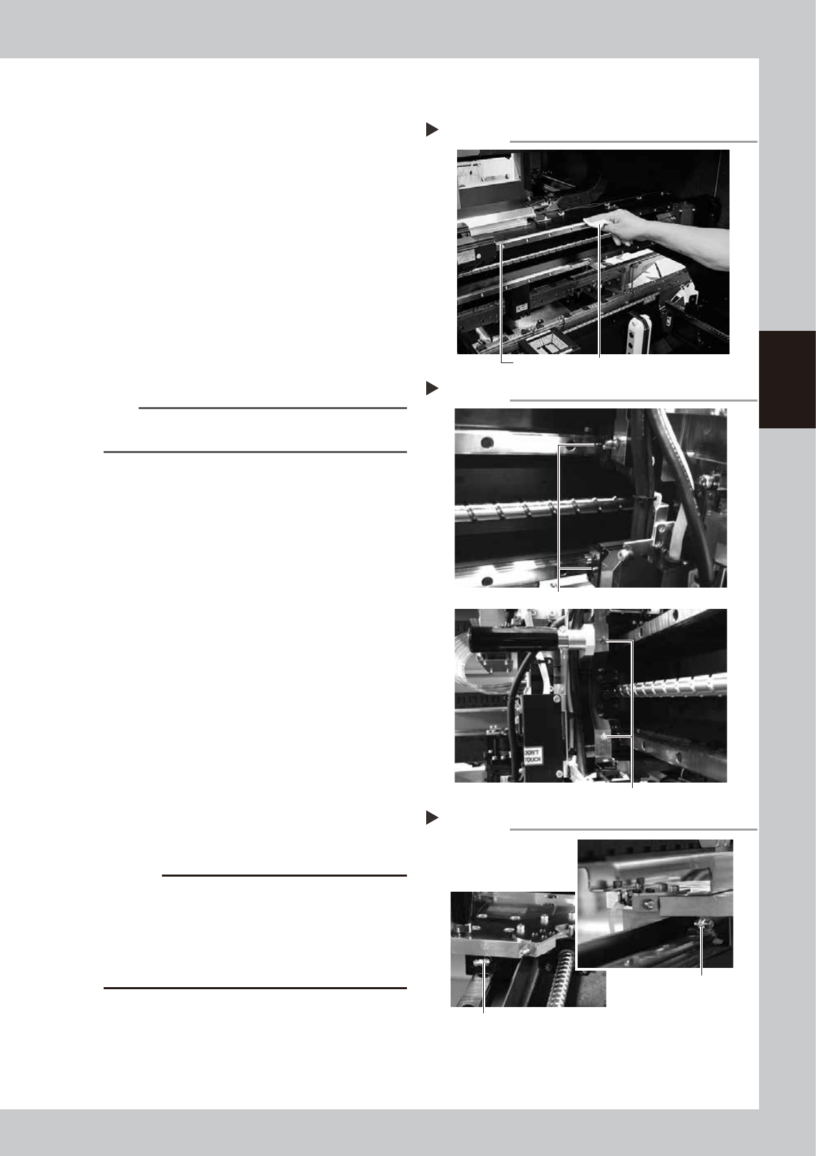
Clean the guides.
1. After moving each axis to the edge,
clean the whole guide with a lint-free
cloth that does not raise dust.
2. Move the axis to the opposite side and
wipe the opposite side guides (X-axis and
Y-axis).
53313-L6-00
n
NOTE
Wipe away thoroughly the old grease in the grooves of
the guide rails.
3
Apply grease to the guides.
1. X-axis
Use the grease gun to apply the
specified grease (NSL) to the X-axis guide
grease nipples.
The grease nipples are located behind
the head unit, 2 each on the right and
left (total of 4 positions). The grease
nipple includes 2 sizes. Attach the
standard or the bent type nozzle to the
grease gun and grease the X-axis guide.
53314-L6-00
2. Y1-axis and Y2-axis
Use the grease gun to apply the
specified grease (NSL) to the Y-axis guide
grease nipples. The grease nipples are
located on the front and back sides of
the slider on each Y-axis guide (total of 4
positions).
Attach the nozzle aligning with the angle
of the grease nipple.
53329-L6-00
c
CAUTION
Align the grease gun nozzle with the angle of the
grease nipple and push the nozzle straight to the nipple
when injecting grease from the bent type grease
nipple. If not aligned, the grease nipple may be
damaged or may come loose and fall off. Carefully
apply the grease.
4
Remove excess grease.
After moving the axis left and right (X-axis)
or back and forth (Y-axis) manually a few
times, wipe away excess grease.
Cleaning the guides
Step 2
Guide rail Wipe with cleaning cloth or paper towel.
Greasing the X-axis guide
Step 3-1
Grease nipple (small)
Grease nipple (large: located on head holder)
Greasing the Y-axis guide
Step 3-2
Grease nipple for
Y-axis guide
Grease nipple for Y-axis guide Total of 4 places