X-Serie S_705.pdf - 第29页
29 Board conveyor I-Placement Alternating placement mode Alternating placement or I-Placement mode Distance of outer conveyor edges: 680 mm, 2 lanes, outer conveyor edges fixed Alternating placement mode Distance of oute…
28
Board conveyor
Technical data
Single conveyor Flexible dual con-
veyor
Dual conveyor in sin-
gle conveyor mode
Board dimensions
(length x width
a
)
a) When using board widths > 450 mm, make sure that the peripheral modules can also process these board widths.
X2 S / X3 S / X4 S - standard 50 mm x 50 mm to
450 mm x 560 mm
50 mm x 50 mm to
450 mm x 320 mm
50 mm x 50 mm to
450mm x 560mm
X2 S / X3 S / X4 S - long board
b
c
b) The "long board option" requires a license.
c) Boards from 650 mm length require an additional input and output conveyor extension.
50 mm x 50 mm to
850 mm x 560 mm
50 mm x 50 mm to
850 mm x 320 mm
50 mm x 50 mm to
850 mm x 560 mm
X4i S - standard
d
d) I-PLacement and alternating placement mode are possible with board lengths up to 380 mm. Only alternating place-
ment mode is possible for boards longer than 380 mm.
50 mm x 50 mm to
380 mm x 560 mm
50 mm x 50 mm to
450 mm x 300 mm
50 mm x 50 mm to
450mm x 510mm
50 mm x 50 mm to
450 mm x 510 mm
50 mm x 50 mm to
380 mm x 320 mm
--
X4i S - long board
b
50 mm x 50 mm to
610 mm x 510 mm
50 mm x 50 mm to
610 mm x 300 mm
50 mm x 50 mm to
610 mm x 510 mm
Stationary conveyor side Right or left Right, left or outer
Automatic electrical width adjust-
ment
Standard
PCB thickness
Standard: 0.3 mm to 4.5 mm
PCB warpage See page 30
PCB weight
e
Standard
e) The board weight value refers to the weight of the board plus the weight of the components.
Max. 3.0 kg Max. 2.0 kg Max. 2.0 kg
Clearance on PCB underside 25 mm
PCB conveyor height
Option:
Standard:
SMEMA option:
900 mm
930 mm
950 mm
Type of interface:
Standard:
Option:
SMEMA
Siemens
Component-free PCB handling
edge
3 mm
PCB changeover time
Single conveyor
Dual conveyor
f
f) 0 seconds in asynchronous mode, otherwise 1.5 seconds.
< 1.5 seconds
0 seconds
Important notes
When setting up a machine (S; F-, HS-, HF-, X- or D-Series) next to a SIPLACE X-Series, be aware that there is limited room
between the two machines. In these cases, use suitable conveyor extensions to create room of 0.5m for the operator between the
two machines.
To achieve top placement performance, fit the first machine in a SIPLACE X-Series line with an input conveyor extension and the
last machine in the line with an output conveyor extension.
29
Board conveyor
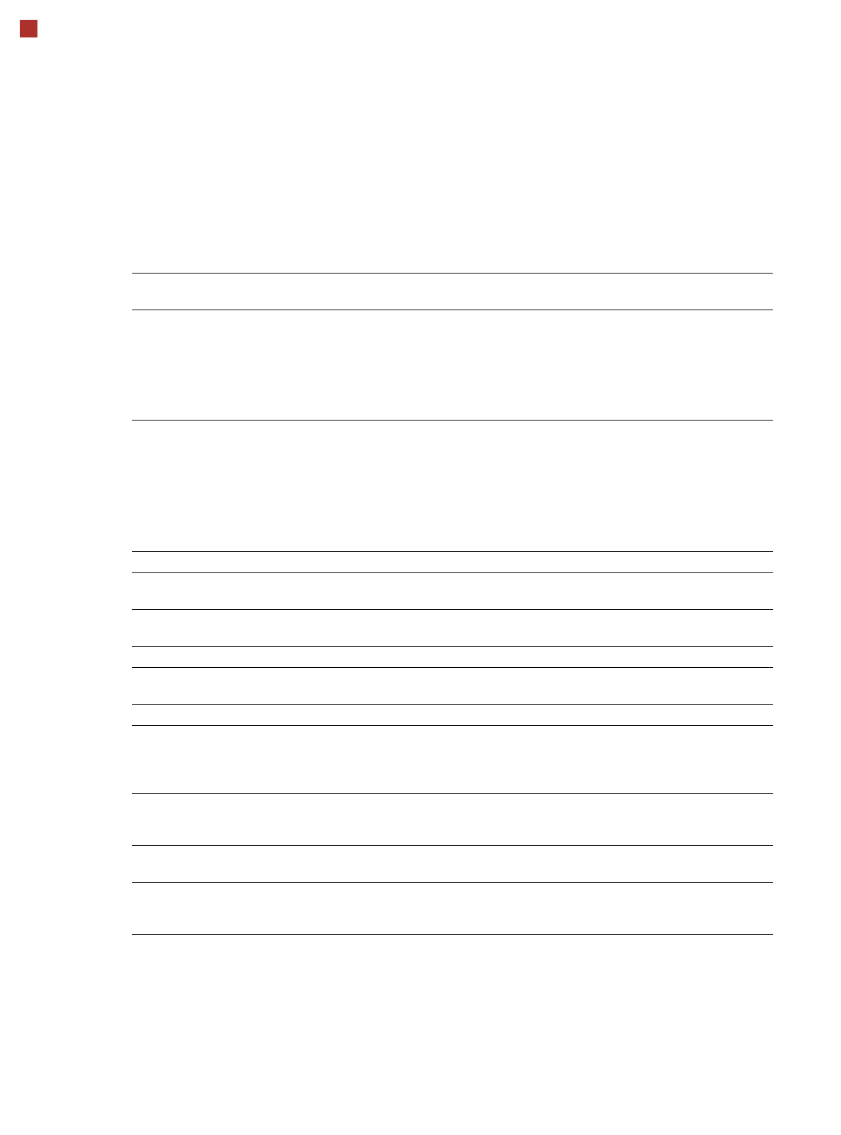
I-Placement
Alternating placement mode
Alternating placement or
I-Placement mode
Distance of outer conveyor
edges: 680 mm, 2 lanes, outer
conveyor edges fixed
Alternating placement mode
Distance of outer conveyor
edges: 601 mm, dual conveyor
in single conveyor mode, right
conveyor edge fixed
a
max. 320
Movable conveyor side
Stationary conveyor side
a) The diagram only shows settings with a fixed righthand conveyor edge. A setting with the stationary conveyor
edge on the left is also possible. All dimensions in millimeters.
max. 320
344
680 (27“)
min. 35
-344
+258
max. 601
Adjustable conveyor side position and max. PCB width
Conveyor side position Max. PCB width
234.2 mm 216 mm
254 mm 236 mm
268 mm 250 mm
281 mm 260 mm
320 mm 300 mm
344 mm 320 mm
Customized (up to max. 344 mm) 320 mm
30
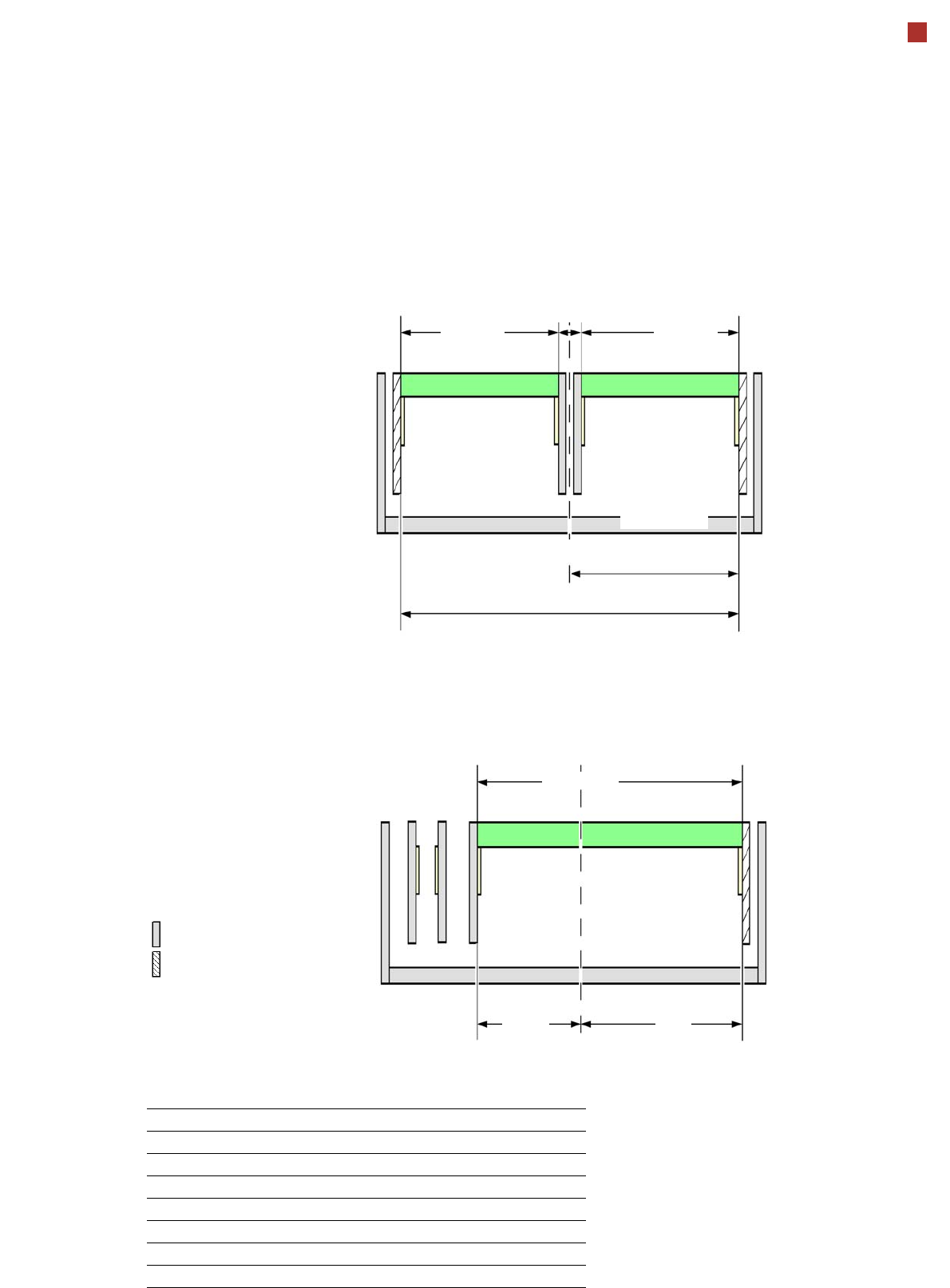
PCB warpage
PCB warpage across the direction of travel
max. 1 % of the PCB diagonal, but not
exceeding 2 mm
PCB warpage on the conveyor
Fixed clamped edge
Movable clamping device
PCB
Fixed clamped edge
Conveyor belt
PCB transport direction
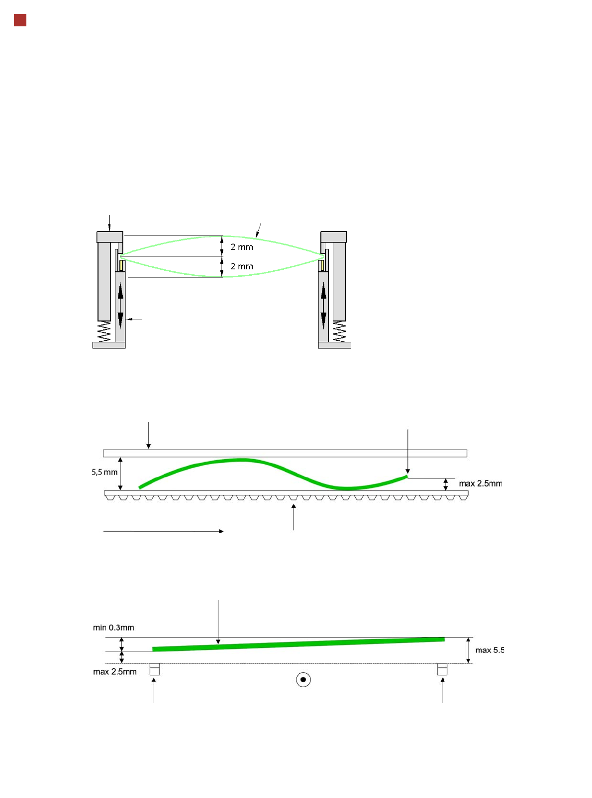
Front board edge
Front board edge
PCB warpage in direction of travel + PCB thickness < 5.5 mm
Bending up of front board edge max. 2.5 mm
Left conveyor belt
Right conveyor belt
PCB transport direction