X-Serie S_705.pdf - 第30页
30 PCB warpage PCB warpage across the directio n of travel max. 1 % of the PCB diagonal, but no t exceeding 2 mm PCB warpage on the convey or Fixed clamped edge Movable clamping device PCB Fixed clamped ed ge Conveyor be…
29
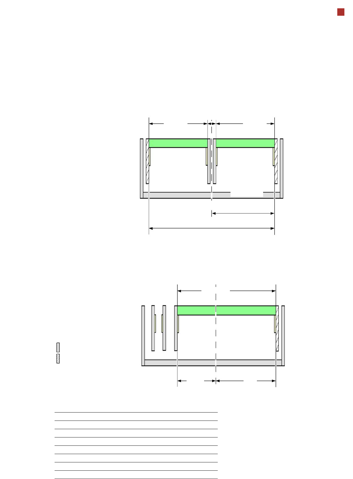
Board conveyor
I-Placement
Alternating placement mode
Alternating placement or
I-Placement mode
Distance of outer conveyor
edges: 680 mm, 2 lanes, outer
conveyor edges fixed
Alternating placement mode
Distance of outer conveyor
edges: 601 mm, dual conveyor
in single conveyor mode, right
conveyor edge fixed
a
max. 320
Movable conveyor side
Stationary conveyor side
a) The diagram only shows settings with a fixed righthand conveyor edge. A setting with the stationary conveyor
edge on the left is also possible. All dimensions in millimeters.
max. 320
344
680 (27“)
min. 35
-344
+258
max. 601
Adjustable conveyor side position and max. PCB width
Conveyor side position Max. PCB width
234.2 mm 216 mm
254 mm 236 mm
268 mm 250 mm
281 mm 260 mm
320 mm 300 mm
344 mm 320 mm
Customized (up to max. 344 mm) 320 mm
30
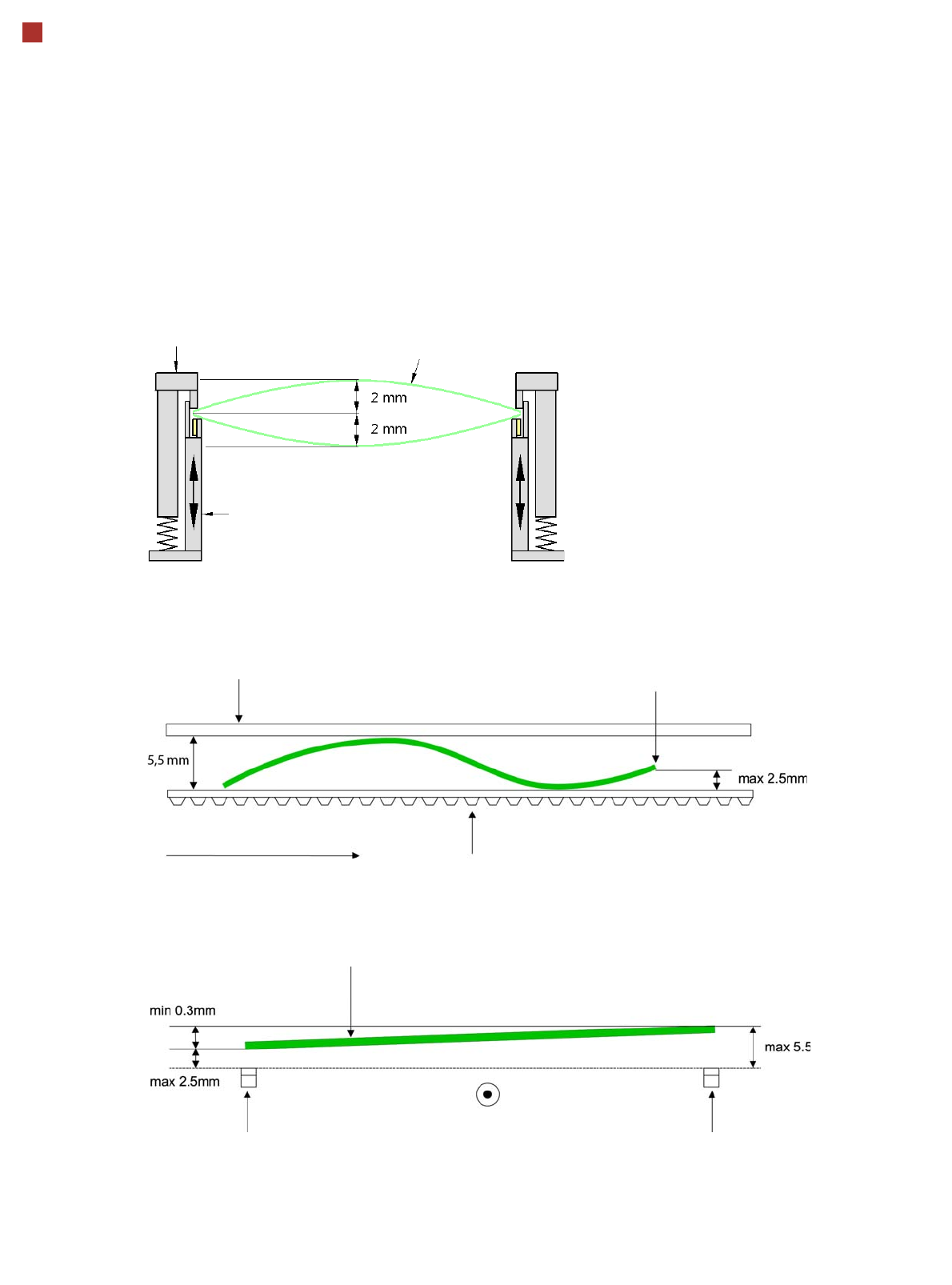
PCB warpage
PCB warpage across the direction of travel
max. 1 % of the PCB diagonal, but not
exceeding 2 mm
PCB warpage on the conveyor
Fixed clamped edge
Movable clamping device
PCB
Fixed clamped edge
Conveyor belt
PCB transport direction
Front board edge
Front board edge
PCB warpage in direction of travel + PCB thickness < 5.5 mm
Bending up of front board edge max. 2.5 mm
Left conveyor belt
Right conveyor belt
PCB transport direction
31
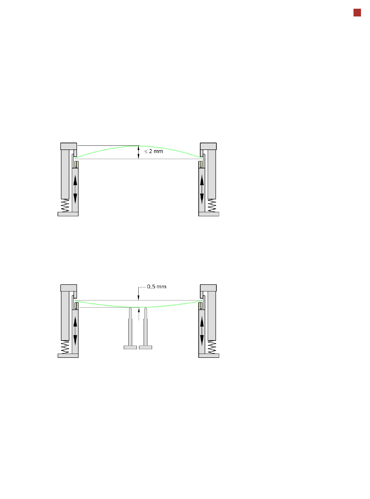
PCB warpage
PCB warpage during placement
PCB warpage downwards max. 0.5 mm
Use the magnetic pin supports, to achieve
this value.
When there is warpage under 2 mm, the
inkspots in the center of the board are also
within the focus of the digital camera. When
all the tolerances are taken into account,
this value is reduced to 1.5 mm.
You should also note that the warpage
reduces the component height.
Magnetic pin support