JAKA Zu 12及JAKA Zu 12 pro -电控柜V2.1-硬件手册(英文版).pdf - 第28页
JAKA Zu 12 v 1.0 23 3 D O 11 1 1th digital o utput, P N P Ty p e , ≤ 1A c ontinuo us current out put capab ility 4 DO12 12th digital outp ut, P N P Ty p e , ≤ 1A conti nuous current out put capab ility 5 DO13 13th digita…
22 JAKA Zu 12 v1.0
Electrical control cabinet front panel interface definition table:
Index Name PIN Label Description
P1
DI(1~8)
Digital Input
1 DI1 1st digital input, PNP Type, the input is active high
2 DI2 2nd digital input, PNP Type, the input is active high
3 DI3 3rd digital input, PNP type, the input is active high
4 DI4 4th digital input, PNP Type, the input is active high
5 DI5 5th digital input, PNP Type, the input is active high
6 DI6 6th digital input, PNP Type, the input is active high
7 DI7 7th digital input, PNP type, the input is active high
8 DI8 8th digital input, PNP type, the input is active high
9~16 V+
The isolated power input is positive, and the factory
default is 24V internal.
P2
DO(1~8)
Digital Output
1 DO1
1st digital output, PNP Type, ≤1A continuous
current output capability
2 DO2
2nd digital output, PNP Type, ≤1A continuous
current output capability
3 DO3
3rd digital output, PNP Type, ≤1A continuous
current output capability
4 DO4
4th digital output, PNP Type, ≤1A continuous
current output capability
5 DO5
5th digital output, PNP Type, ≤1A continuous
current output capability
6 DO6
6th digital output, PNP Type, ≤1A continuous
current output capability
7 DO7
7th digital output, PNP Type, ≤1A continuous
current output capability
8 DO8
8th digital output, PNP Type, ≤1A continuous
current output capability
9~16 V-
Isolated power input negative, default shorting is
connected to internal GND
P3
DI(9~16)
Digital Input
1 DI9
9th digital input, PNP Type, the input is active high
2 DI10 10th digital input, PNP Type, the input is active high
3 DI11 11th digital input, PNP Type, the input is active high
4 DI12 12th digital input, PNP Type, the input is active high
5 DI13 13th digital input, PNP Type, the input is active high
6 DI14 14th digital input, PNP Type, the input is active high
7 DI15 15th digital input, PNP Type, the input is active high
8 DI16 16th digital input, PNP Type, the input is active high
9~16 V+
The isolated power input is positive, and the factory
default is 24V internal
P4
DO(9~16)
Digital Output
1 DO9
9th digital output, PNP Type, ≤1A continuous
current output capability
2 DO10
10th digital output, PNP Type, ≤1A continuous
current output capability
JAKA Zu 12 v1.0 23
3 DO11
11th digital output, PNP Type, ≤1A continuous
current output capability
4 DO12
12th digital output, PNP Type, ≤1A continuous
current output capability
5 DO13
13th digital output, PNP Type, ≤1A continuous
current output capability
6 DO14
14th digital output, PNP Type, ≤1A continuous
current output capability
7 DO15
15th digital output, PNP Type, ≤1A continuous
current output capability
8 DO16
16th digital output, PNP Type, ≤1A continuous
current output capability
9~16 V-
Isolated power input negative, default shorting is
connected to internal GND
P5 AI/O
1、4
5VA
Analog power supply 5V output, 100mA (max)
2 Ch1 Analog input/output channel 1
3 Ch2 Analog input/output channel 1
5~8 AG Analog ground
P6 HSI
1、8
5VD
Digital power supply 5V output, 100mA (max)
2、3 1P Differential signal 1 input positive / encoder A +
14、15
1N
Differential signal 1 input negative / encoder A-
4、5
2P
Differential signal 2 input positive / encoder B+
12、13 2N Differential signal 2 input negative / encoder B-
6、7
3P
Differential signal 3 input positive / encoder Z +
10、11 3N Differential signal 3 input negative / encoder Z-
9、16
DG
Digital ground
P7 -
1、2 VSB
Internal power supply 5V, 100mA (max), can be
used for remote power on/off
3 0V Internal GND (internal 24V, 12V reference ground)
4、5
485B
RS485 B
6、7
485A RS485 A
8 V-
Isolated power input negative, default shorting is
connected to internal GND
9 OFF
Remote shutdown signal input, high level (5~24V) is
valid
10 ON
Remote power-on signal input, high level (5~24V) is
valid
P8 -
1~4、8 V+
Isolated power input is positive, factory default is
connected to internal 24V
5 24V
The internal 24V output is positive and supports a
maximum of 1.5A current output
24 JAKA Zu 12 v1.0
6 0V The internal 24V power supply output is negative
7 V-
The isolated power input is negative, and the factory
default is connected to the internal GND
9 SI2
The protection stop function input 2, the factory
default is V+
10 SI1
The protection stop function input 2, the factory
default is V+
11 EI2
Emergency stop function input 2, the factory default
is V+
12 EI1
Emergency stop function input 1, the factory default
is V+.
P9 - - USB USB3.0
P10 - - Ethernet1 Gigabit Ethernet interface
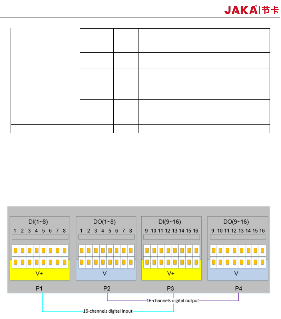
4.3.1 All digital I/O common specifications
This section describes the electrical specifications for 24V digital I/O using an electrical cabinet. Can be
divided into: V + power selection, security I / O configuration.
The electrical cabinet supports 16 digital inputs and 16 digital outputs, as shown in Figure 4-2.
Fi
gure 4-2
The digital I/O can be powered by a 24V power supply provided inside the control cabinet and supports up
to 1.5A output (overload will turn off the output). When the user needs more power output, the V+ power supply
can be powered by an external "24V power supply". 24V is the internal power supply and 0V is the internal
ground. V+ is the positive pole of the digital I/O interface, and V- is the negative pole of the digital I/O interface.
The factory default configuration is internal power, see Figure 4-3 below.