TS5540-user-guide.pdf - 第3页
9 8. 예비 부품 및 액세서리 TS5540/TS5540F 예비 부품 및 액세서리 정보는 다음 주소의 TS5540/TS5540F 사용설명서 웹페이지를 확인하시기 바랍니다. http://www.techconsystems.co m/literature/lit_manuals.cfm 9. 제한 보증 OK International 은 최초 구매자를 대상으로 소재 및 제조상의 결함에 한해 1 년 동안 본…
2
CONTENTS
Page number
1. Safety ................................................................................ 1
2. Specifications ................................................................... 3
3. Features ............................................................................ 3
4. Connecting the Valve ....................................................... 4
5. Operating Instructions .................................................. 4-5
6. Troubleshooting ................................................................ 6
7. Maintenance and Cleaning ......................................... 7 - 8
8. Spare Parts and Accessories ............................................. 9
9. Limited Warranty ............................................................. 9
1. SAFETY
1.1 Intended Use:
WARNING: Use of this equipment in ways other than those described in this
User Guide may result in injury to person or damage to property. Use this
equipment only as described in this User Guide or in the TS5540 User Guide
webpage at http://www.techconsystems.com/literature/lit_manuals.cfm
OK International cannot be responsible for injuries or damages resulting from
unintended applications of its equipment. Unintended uses may result from
taking the following actions:
• Making changes to equipment that has not been recommended in the
User Guide
• Using incompatible or damaged replacement parts
• Using unapproved and/or unsafe accessories, auxiliary equipment and
attachment materials and methodology
1.2 Safety Precautions:
• Do not operate this unit in excess of maximum ratings/settings
• Always wear appropriate personal protective eyewear, clothing or
apparel when operating or cleaning/servicing the equipment
• The fluid being dispensed may be toxic and/or hazardous. Refer to
Material Safety Data Sheet for proper handling and safety precautions
9
8. 예비 부품 및 액세서리
TS5540/TS5540F 예비 부품 및 액세서리 정보는 다음 주소의
TS5540/TS5540F 사용설명서 웹페이지를 확인하시기 바랍니다.
http://www.techconsystems.com/literature/lit_manuals.cfm
9. 제한 보증
OK International 은 최초 구매자를 대상으로 소재 및 제조상의 결함에 한해
1 년 동안 본 제품을 보증하여 드리되, 일반적인 마모나 긁힘, 오용 및
잘못된 설치로 인한 장비 손상 등은 제외합니다. 보증에 의거하여 결함이
있는 제품이나 부속품 및 부품은 (OK International 의 옵션에 따라) 무료로
수리 또는 교환해 드립니다. 보증에 따라 결함이 있는 제품을 구매하신
고객께서는 지정된 OK International 공인 서비스 센터로 제품을 보내시기
전에 가까운 OK International 사무소나 유통 업체에 연락하셔서 반품
인증을 받아주시기 바랍니다. 가장 가까운 OK International 사무소나 유통
업체에 관한 정보는 www.techconsystems.com 을 방문하셔서 확인할 수
있습니다. OK International 은 통보 없이 엔지니어링 제품을 변경할 권리를
가지고 있습니다.
TSI-0267A_B
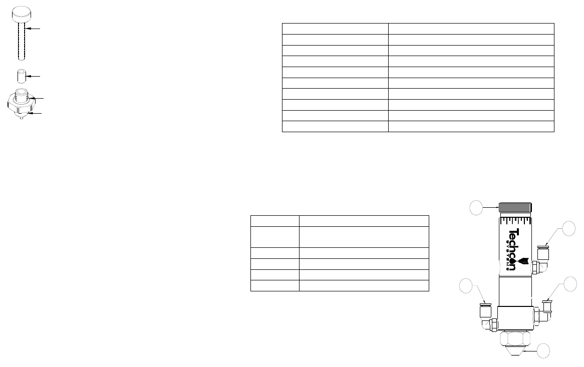
그림 4.0
노즐
O 링
시트
손나사
Nozzle
Seat
Thumb Screw
O-ring
3
2. SPECIFICATIONS
Teflon® and Delrin® are registered trademarks of E.I. DuPont.
3. FEATURES
Size 104.1 x 25.4 mm (4.1” x 1.0”)
Weight 331g (0.73lb)
Fluid Inlet Port 1/8” NPT female
Air Inlet Port 10-32 UNF-2B
Atomize Air Inlet Port 10-32 UNF-2B
Fluid Pressure 100 psi (6.9 bar) maximum
Activation Pressure 70 psi (4.8 bar) minimum
Wetted Parts 303 stainless steel, Delrin®, Teflon®
Air Cylinder Material 303 stainless steel
Operating Frequency Exceeds 400 cycles/min.
Items # Description
1 Stroke Control Adjustment
Knob
2 Valve-actuating Air Inlet Port
3 Fluid Inlet Port
4 Removable Spray Cap
5 Atomize Air Inlet Port
2
3
5
4
1
Figure 1.0
4
4. CONNECTING THE VALVE
5. OPERATING INSTRUCTIONS
1. Set valve air pressure at Valve Controller to 70 psi (4.8 bar).
2. Set the atomize air pressure at Valve Controller according to the viscosity of fluid
being spray.
3. Set fluid pressure at Fluid Reservoir according the viscosity of fluid being sprayed;
do not exceed 100 psi (6.9 bars).
4. Place a waste bucket under the valve spray nozzle and purge the valve until the
fluid flows steadily.
Spray coverage is determined by:
• Stroke control adjustment – Rotate Stroke Control Knob clockwise to
decrease flow rate and counterclockwise to increase flow rate. DO NOT
rotate the knob beyond the “Line Marker” which is labeled on the knob
shaft.
• Length of actuation as set at Valve Controller (the “valve-on” time)
• Fluid reservoir pressure
• Fluid viscosity
• Distance between the spray nozzle and the sprayed surface
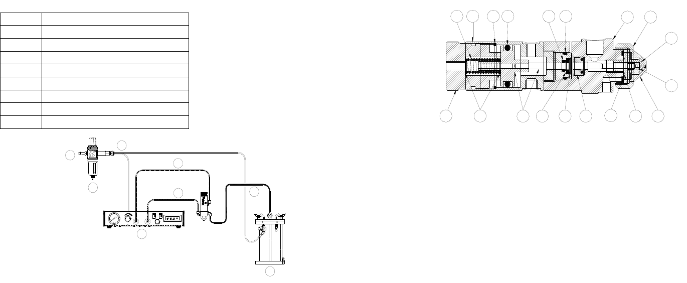
Item # Description
1 From air source
2 Air Filter (optional)
3 Constant air flow
4 Valve Air Hose (included)
5 Atomize Air Hose (included)
6 Fluid Feed Hose (optional)
7 Fluid Reservoir (TS1258 - optional)
8 Valve Controller (TS500R - optional)
MODE/TIME DISPLAY
MODE DECIMAL
MODE/TIME SET
1
2
7
8
4
5
6
3
TS5540
Figure 2.0
8
7.3 노즐 및 공기 캡 교체(그림 3.0 참조)
1. 행정 제어 조정 손잡이(19)를 시계 반대 방향으로 '표시선' 너머까지
돌려 분해하십시오.
2. 압축 스프링(1)과 압축 스프링의 양 끝에 있는 두 개의 Mylar
Washer(18)를 분해하십시오.
3. 오픈 엔드 렌치를 이용해 잠금 캡(8)을 분리한 다음, 유체
하우징(7)에서 공기 캡(11)을 잡아 당기십시오.
4. 오픈 엔드 렌치를 이용해 낡은 노즐(9)과 스페이서(13)를
분해하십시오.
5. 스페이서(13)를 다시 조립하고 오픈 엔드 렌치를 이용해 새로운
노즐(9)을 조립하십시오. 노즐에 O 링이 있는지 확인하십시오. 노즐을
너무 꽉 조이지 마십시오.
6. 새로운 공기 캡(11)을 조립한 다음, 잠금 캡(8)으로 조이십시오.
7.4 시트 교체(그림 4.0 참조 )
1. 손나사를 노즐(9)에 넣고 시계 방향으로 돌려 시트(10)에
부착시키십시오.
2. '소프트 조'에 노즐을 단단히 고정시킨 다음, 손나사를 시트가 부착된
채로 똑바로 빼십시오.
3. 새로운 시트를 손나사에 끼운 다음, 나사를 노즐에 똑바로
삽입하십시오. 시트가 제대로 정렬되도록 하기 위해서 시트 설치
작업은 Arbor Press 에서 할 것을 권장합니다.
그림 3.0
12
7
6534
12 11
8
9
10
13
14151617
1819