TS5540-user-guide.pdf - 第6页
6 6. TROUBLESHOOTING PROBLEM POSSIBLE CAUSE CORRECTION No fluid flow Fluid pressure too low Increase fluid pres sure at Fluid Reservoir Operating pressure too low Increase air press ure to 70 psi (4.8 bars) at Valve Cont…
7
8. 부드러운 솔을 이용해 유체 하우징(7), 바늘/피스톤 부품(17) 및
노즐(9)을 이소프로필 알코올로 닦으십시오.
9. 밸브가 새고 있으면 손나사(TD1113-28)를 이용해 시트(10)를
분리하고 새 것으로 교체하십시오. 교체 방법은 7.4 '시트 교체'
단락을 지침으로 참조하십시오.
10. 유체 하우징(7)에 노즐(9), 스페이서(13), 공기 캡(11)을 다시
조립하십시오.
11. 그리스를 O 링(6)에 칠한 다음, 공기 실린더/바늘 부품(2)을 유체
하우징(7)에 다시 조립하십시오.
12. 압축 스프링(1)을 다시 조립하려면 먼저 Mylar Washer 하나를
바늘/피스톤 부품(17) 위에 놓고 다른 Mylar Washer 는 행정 제어
조정 손잡이(18)에 놓은 다음, 압축 스프링을 조립하십시오.
13. 행정 제어 조정 손잡이(19)를 다시 조립하려면 시계 방향으로 멈출
때까지 돌린 다음, 원하는 설정에 맞게 다시 시계 반대 방향으로
돌리십시오. 하지만 손잡이 축에 있는 '표시선'은 넘지 마십시오.
7.1 바늘/피스톤 부품 및 씰 교체(그림 3.0 참조)
1. 이전 단락의 1 ~ 7 단계를 따라 하십시오(7.1 단락).
2. O 링(6)이 손상되었다면 교체하십시오.
3. 유체 하우징(7)에서 컵 씰(14)을 분해하십시오.
4. 스냅링 플라이어를 이용해 첫 번째 리테이닝링(3)을 분해하십시오.
5. 바늘/피스톤 부품(17)을 공기 실린더(2)에서 똑바로 잡아 당기십시오.
6. 스냅링 플라이어를 이용해 두 번째 리테이닝링(15)을 분해하십시오.
7. Nylon Washer(16)와 O 링(5)을 분해하십시오. 이 부품들이
손상되었다면 교체하십시오.
8. O 링(5), Nylon Washer(16)를 다시 조립하고 리테이닝링(14)으로
조이십시오.
9. 바늘/피스톤 부품(17)을 다시 조립하고 다른 리테이닝링(3)으로
조이십시오.
10. 나무 못과 같은 부드러운 막대를 이용해 컵 씰(14)을 유체
하우징(7)에 다시 조립하십시오.
11. 이전 단락의 9 ~ 13 단계를 따라 하십시오(7.1 단락).
5
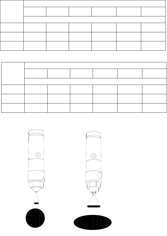
Round Pattern
(Approximation)
Fan Pattern
(Approximation)
SPRAY AREA COVERAGE BY ROUND NOZZLE*
SPRAY AREA COVERAGE BY FAN NOZZLE*
*Spray area coverage shown in above charts is for reference only. Actual coverage area depends on
fluid viscosity and characteristics
Nozzle size
Distance from Sprayed Surface
1”
(25.40mm)
2”
(50.80mm)
3”
(76.20mm)
4”
(101.60mm)
5”
(127.00mm)
6”
(152.40mm)
Spray area coverage (diameter)
0.046”
(1.17mm)
0.25”
(6.35mm)
0.50”
(12.70mm)
0.75”
(19.05mm)
1.00”
(25.40mm)
1.25”
(31.75mm)
1.50”
(38.10mm)
0.028”
(0.71mm)
0.20”
(5.08mm)
0.40”
(10.16mm)
0.60”
(15.24mm)
0.80”
(20.32mm)
1.00”
(25.40mm)
1.20”
(30.48mm)
0.014”
(0.36mm)
0.17”
(4.32mm)
0.34”
(8.64mm)
0.50”
(12.70mm)
0.65”
(16.51mm)
0.85”
(21.59mm)
1.00”
(25.40mm)
Nozzle size
Distance from Sprayed Surface
1”
(25.40mm)
2”
(50.80mm)
3”
(76.20mm)
4”
(101.60mm)
5”
(127.00mm)
6”
(152.40mm)
Spray area coverage (major diameter)
0.046”
(1.17mm)
1.00”
(24.40mm)
1.50”
(38.10mm)
2.40”
(61.00mm)
3.00”
(76.20mm)
4.00”
(101.60mm)
4.25”
(108.00mm)
0.028”
(0.71mm)
0.65
(16.51mm)
1.25”
(31.75mm)
1.50”
(38.10mm)
2.00”
(50.80mm)
2.50”
(63.50mm)
3.25”
(82.55mm)
0.014”
(0.36mm)
0.50”
(12.70mm)
1.00”
(24.40mm)
1.25”
(31.75mm)
1.60”
(40.64mm)
2.00”
(50.80mm)
2.50”
(63.50mm)
6
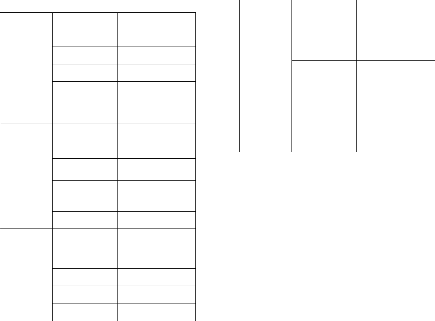
6. TROUBLESHOOTING
PROBLEM POSSIBLE CAUSE CORRECTION
No fluid flow
Fluid pressure too low
Increase fluid pressure at Fluid
Reservoir
Operating pressure too
low
Increase air pressure to 70 psi
(4.8 bars) at Valve Controller
Valve is not actuating
Check Valve Controller for air
pressure level to valve
Fluid cured in valve
chamber
Disassemble and clean valve
thoroughly
Stroke control adjustment
not activating or engaged
Engage by rotating the Stroke
Control Adjustment Knob
counterclockwise (but not
b
e
y
ond the “Line Marker”
)
Inconsistent
fluid flow
Fluid pressure fluctuating
Make sure fluid pressure is
constant
Valve operating pressure
is too low
Increase valve pressure to 70 psi
(4.8 bars) at Valve Controller
Valve opening time is not
consistent
Check to make sure the Valve
Controller is providing a
consistent air pressure output
Air trapped in Fluid
Housing
Purge air from valve
Fluid drools after
the valve closes,
eventually stopping
Air trapped in Fluid
Housing
Purge air from valve
Post-spray time is too
short
Increase post-spray time at
Valve Controller
Fluid flows through
nozzle but will not
spray
Atomize pressure is too
low
Increase atomizing pressure at
Valve Controller
Steady drip
Dirty Needle and Delrin®
Seat
Thoroughly clean Needle and
Seat
Delrin® Seat is worn or
damaged
Replace worn or damaged part
Fluid pressure exceeds
100 psi (6.9 bars)
Lower fluid pressure at Fluid
Reservoir until dripping stops
Valve reassembled
incorrectly
Disassemble and reassemble
valve according to instructions
6
유체가 노즐을
통해 흐르지만
분사되지
않습니다.
분사 압력이 너무
낮습니다.
밸브 제어기에서 분사 압력을
높이십시오.
유체가 계속 뚝뚝
떨어집니다.
바늘과 Delrin® 시트가
더러워졌습니다.
바늘과 시트를 깨끗이
청소하십시오.
Delrin® 시트가
낡았거나
손상되었습니다.
낡거나 손상된 부품을
교체하십시오.
유압이 100 psi(6.9
bars)를 초과했습니다.
유체가 떨어지지 않을 때까지
유체 저장소에서 유압을
낮추십시오.
밸브가 잘못
재조립되었습니다.
밸브를 지침에 따라 분해하고
다시 조립하십시오.
7. 유지보수 및 청소
필요한 도구/재료(각각 하나씩): 오픈 엔드 렌치, 스냅링 플라이어, 부드러운 솔,
O 링 그리스, 나무 못 및 손나사(P/N=TSD1113-28); 권장 세제: 이소프로필
알코올이나 비슷한 용제
7.1 전체 청소(그림 3.0 참조)
1. 유체 저장소에서 유압을 빼십시오.
2. 밸브에서 유체 라인과 밸브 공기 호스를 분리하십시오.
3. 행정 제어 조정 손잡이(19)를 시계 반대 방향으로 '표시선' 너머까지
돌려서 분해하십시오. 압축 스프링이 손잡이를 밀어서 느슨해집니다.
4. 압축 스프링(1)과 압축 스프링의 양 끝에 있는 두 개의 Mylar
Washer(18)를 분해하십시오.
5. 오픈 엔드 렌치를 이용해 잠금 캡(8)을 분리한 다음, 유체
하우징(7)에서 공기 캡(11)을 잡아 당기십시오.
6. 오픈 엔드 렌치를 이용해 스페이서(13)와 노즐(9)을 분해하십시오. O
링이 손상되었으면 교체하십시오.
7. 유체 하우징(7)을 잡고 공기 실린더/바늘 부품(2)을 시계 반대
방향으로 돌리십시오. 완전히 풀리면 두 개의 밸브 부분을 따로따로
똑바로 잡아 당겨 분리하십시오.
5
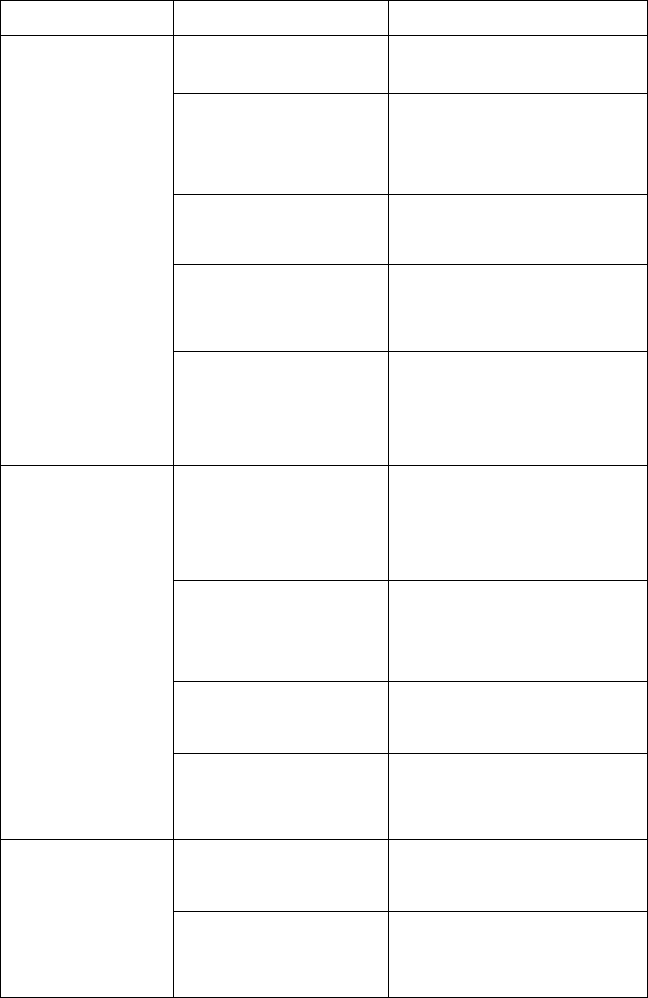
6. 문제 해결
문제 가능한 원인 해결책
유체가 나오지
않음
유압이 너무 낮습니다.
유체 저장소의 유압을
높이십시오.
작동 압력이 너무
낮습니다.
밸브 제어기에서 공기압을 70
psi(4.8 bars)로 높이십시오.
밸브가 가동하지
않습니다.
밸브 제어기에서 밸브의
공기압 수준을 점검하십시오.
밸브 Chamber 의
유체가 굳어 있습니다.
밸브를 분해해서 깨끗하게
청소하십시오.
행정 제어 조정이
활성화되지 않거나
작동하지 않습니다.
행정 제어 조정 손잡이를
시계 반대 방향으로 돌려서
작동시키십시오. ('표시선'
너머로 돌리지 마십시오.)
불안정한 유체
흐름
유압 불안정
유압이 일정한지
확인하십시오.
밸브 작동 압력이 너무
낮습니다.
밸브 제어기에서 밸브 압력을
70 psi(4.8 bars)로
높이십시오.
밸브 개방 시간이
일정하지 않습니다.
밸브 제어기가 일정한
공기압을 유지하고 있는지
확인하십시오.
공기가 유체 하우징에
남아 있습니다.
밸브에서 공기를
제거하십시오.
밸브가 닫히고 난
후 유체가 흘러
나오다 멈춥니다.
공기가 유체 하우징에
남아 있습니다.
밸브에서 공기를
제거하십시오.
분사 후 시간이 너무
짧습니다.
밸브 제어기에서 분사 후
시간을 늘리십시오.
7
7. MAINTENANCE AND CLEANING
Tool/Material required (one each): open-end wrench, snap-ring pliers, soft brush, o-
ring grease, wooden dowel and Thumb Screw (P/N=TSD1113-28); cleaning agent
recommended: Isopropyl Alcohol or equivalent solvent.
7.1 Thorough Cleaning (See Figure 3.0)
1. Release fluid pressure at Fluid Reservoir.
2. Disconnect fluid line and valve air hoses from valve.
3. Remove Stroke Control Adjustment Knob (19) by rotating it
counterclockwise beyond the “Line Marker;” the knob is loosen as it is
pushed by the Compression Spring.
4. Remove the Compression Spring (1) and the two Mylar Washers (18) on
each end of the Compression Spring.
5. Using the open-end wrench to remove the Locking Cap (8) and then pull the
Air Cap (11) out from the Fluid Housing (7).
6. Using the open-end wrench to remove the Nozzle (9) along with the Spacer
(13); replace O-ring if it is damaged.
7. Hold Fluid Housing (7) and rotate the Air Cylinder/Needle Assembly (2)
counterclockwise. When completely un-threaded, pull the two valve
segments straight apart to separate.
8. Using the soft brush to clean Fluid Housing (7), Needle/Piston Assembly (17)
and Nozzle (9) with Isopropyl Alcohol.
9. If the valve is leaking, using the Thumb Screw (TSD1113-28) to remove the
Seat (10) and replace it with a new one; refer to Section 7.4 “Seat
Replacement” for instructions.
10. Reinstall Nozzle (9), Spacer (13), Air Cap (11) and Locking Cap (8) into
Fluid Housing (7).
11. Lubricate O-ring (6) with grease then reassemble the Air Cylinder/Needle
Assembly (2) into Fluid Housing (7).
12. To reinstall Compression Spring (1) by first placing one Mylar Washer over
the Needle/Piston Assembly (17), then the other Mylar Washer into the
Stroke Control Adjustment Knob (18) and followed by the Compression
Spring.
13. Reinstall the Stroke Control Adjustment Knob (19) by rotating it clockwise
until it stops and then counterclockwise to the desired setting BUT NOT
beyond the “Line Marker” on the knob shaft.