TS5540-user-guide.pdf - 第8页
8 7.2 Needle/Piston Assembly and Seal Replacement (See Figure 3.0) 1. Follow Step# 1-7 in previous section (Section 7.1). 2. Replace O-ring (6) if damaged. 3. Remove Cup Seal (14) from Fluid Housing (7). 4. Use the snap-…

5
6. 문제 해결
문제 가능한 원인 해결책
유체가 나오지
않음
유압이 너무 낮습니다.
유체 저장소의 유압을
높이십시오.
작동 압력이 너무
낮습니다.
밸브 제어기에서 공기압을 70
psi(4.8 bars)로 높이십시오.
밸브가 가동하지
않습니다.
밸브 제어기에서 밸브의
공기압 수준을 점검하십시오.
밸브 Chamber 의
유체가 굳어 있습니다.
밸브를 분해해서 깨끗하게
청소하십시오.
행정 제어 조정이
활성화되지 않거나
작동하지 않습니다.
행정 제어 조정 손잡이를
시계 반대 방향으로 돌려서
작동시키십시오. ('표시선'
너머로 돌리지 마십시오.)
불안정한 유체
흐름
유압 불안정
유압이 일정한지
확인하십시오.
밸브 작동 압력이 너무
낮습니다.
밸브 제어기에서 밸브 압력을
70 psi(4.8 bars)로
높이십시오.
밸브 개방 시간이
일정하지 않습니다.
밸브 제어기가 일정한
공기압을 유지하고 있는지
확인하십시오.
공기가 유체 하우징에
남아 있습니다.
밸브에서 공기를
제거하십시오.
밸브가 닫히고 난
후 유체가 흘러
나오다 멈춥니다.
공기가 유체 하우징에
남아 있습니다.
밸브에서 공기를
제거하십시오.
분사 후 시간이 너무
짧습니다.
밸브 제어기에서 분사 후
시간을 늘리십시오.
7
7. MAINTENANCE AND CLEANING
Tool/Material required (one each): open-end wrench, snap-ring pliers, soft brush, o-
ring grease, wooden dowel and Thumb Screw (P/N=TSD1113-28); cleaning agent
recommended: Isopropyl Alcohol or equivalent solvent.
7.1 Thorough Cleaning (See Figure 3.0)
1. Release fluid pressure at Fluid Reservoir.
2. Disconnect fluid line and valve air hoses from valve.
3. Remove Stroke Control Adjustment Knob (19) by rotating it
counterclockwise beyond the “Line Marker;” the knob is loosen as it is
pushed by the Compression Spring.
4. Remove the Compression Spring (1) and the two Mylar Washers (18) on
each end of the Compression Spring.
5. Using the open-end wrench to remove the Locking Cap (8) and then pull the
Air Cap (11) out from the Fluid Housing (7).
6. Using the open-end wrench to remove the Nozzle (9) along with the Spacer
(13); replace O-ring if it is damaged.
7. Hold Fluid Housing (7) and rotate the Air Cylinder/Needle Assembly (2)
counterclockwise. When completely un-threaded, pull the two valve
segments straight apart to separate.
8. Using the soft brush to clean Fluid Housing (7), Needle/Piston Assembly (17)
and Nozzle (9) with Isopropyl Alcohol.
9. If the valve is leaking, using the Thumb Screw (TSD1113-28) to remove the
Seat (10) and replace it with a new one; refer to Section 7.4 “Seat
Replacement” for instructions.
10. Reinstall Nozzle (9), Spacer (13), Air Cap (11) and Locking Cap (8) into
Fluid Housing (7).
11. Lubricate O-ring (6) with grease then reassemble the Air Cylinder/Needle
Assembly (2) into Fluid Housing (7).
12. To reinstall Compression Spring (1) by first placing one Mylar Washer over
the Needle/Piston Assembly (17), then the other Mylar Washer into the
Stroke Control Adjustment Knob (18) and followed by the Compression
Spring.
13. Reinstall the Stroke Control Adjustment Knob (19) by rotating it clockwise
until it stops and then counterclockwise to the desired setting BUT NOT
beyond the “Line Marker” on the knob shaft.
8
7.2 Needle/Piston Assembly and Seal Replacement (See Figure 3.0)
1. Follow Step# 1-7 in previous section (Section 7.1).
2. Replace O-ring (6) if damaged.
3. Remove Cup Seal (14) from Fluid Housing (7).
4. Use the snap-ring pliers to remove the first Retaining Ring (3).
5. Pull the Needle/Piston Assembly (17) straight out from the Air Cylinder (2).
6. Use the Snap-ring pliers to remove the second Retaining Ring (15).
7. Remove the Nylon Washer (16) and O-ring (5); replace these parts if
damaged.
8. Reinstall O-ring (5), Nylon Washer (16) and secure with a Retaining Ring
(14).
9. Reinstall Needle/Piston Assembly (17) and secure with the other Retaining
Ring (3).
10. Reinstall Cup Seal (14) into Fluid Housing (7) using a soft rod (such as a
wooden dowel).
11. Follow Step# 9-13 in previous section (Section 7.1).
7.3 Nozzle and Air Cap Replacement (See Figure 3.0)
1. Remove Stroke Control Adjustment Knob (19) by rotating it
counterclockwise and beyond the “Line Marker” position.
2. Remove the Compression Spring (1) and the two Mylar Washers (18) on
each end of the Compression Spring.
3. Using the open-end wrench to remove the Locking Cap (8) and then pull the
Air Cap (11) out from the Fluid Housing (7).
4. Using the open-end wrench to remove the old Nozzle (9) and Spacer (13).
5. Reinstall Spacer (13) and using the open-end wrench to reinstall new Nozzle
(9), make sure the O-ring is on the Nozzle; do not over tighten the Nozzle.
6. Install new Air Cap (11) and then secure it with the Locking Cap (8).
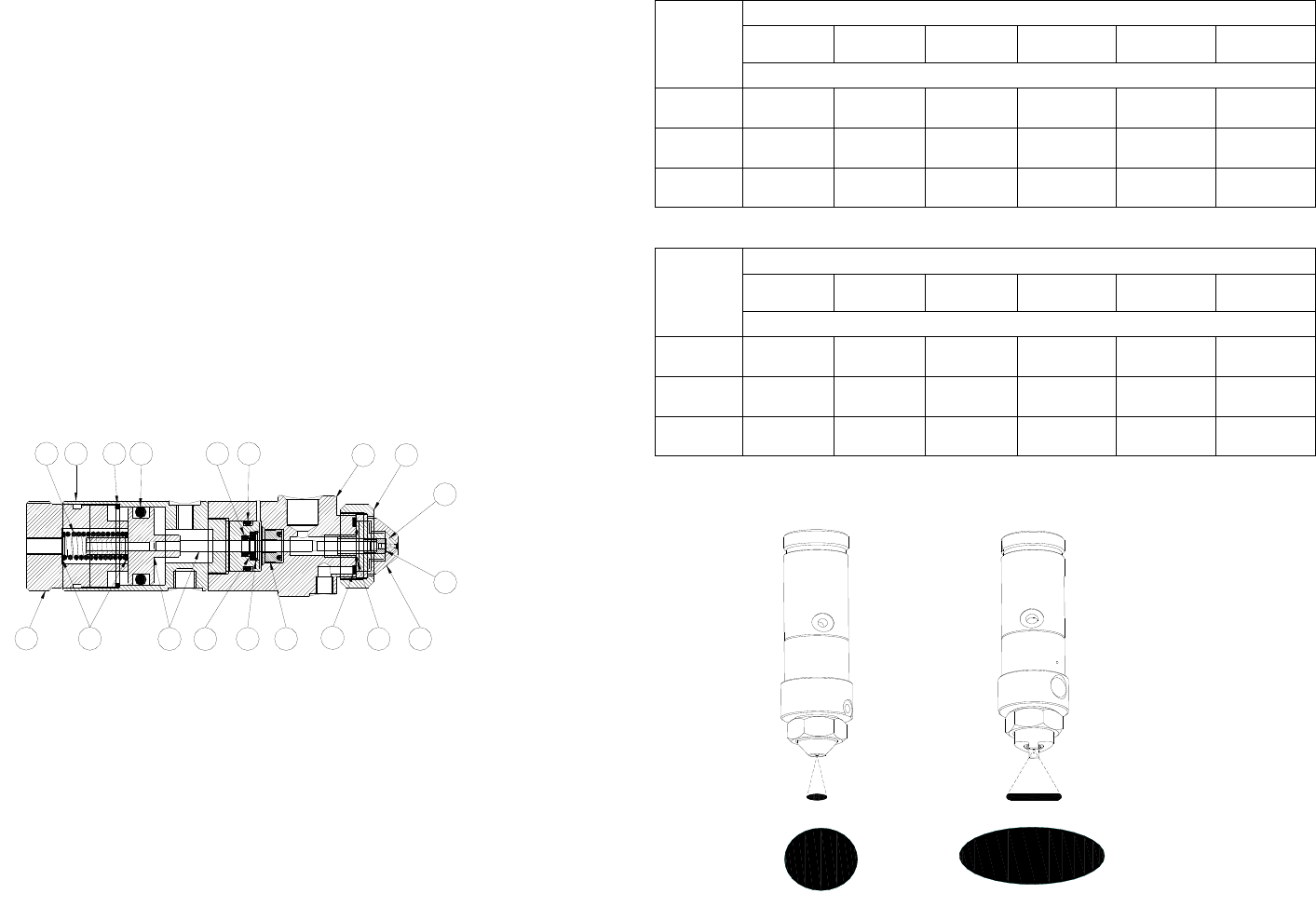
Figure 3.0
12
7
6534
12 11
8
9
10
13
14151617
1819
4
원형 노즐별 분사 영역 범위*
팬 노즐별 분사 영역 범위*
*위 표에 나오는 분사 영역 범위는 단지 참조 사항일 뿐입니다. 실제 범위는 유체 점도 및
특성에 따라 달라집니다.
노즐 크기
분사되는 표면으로부터의 거리
1”
(25.40mm)
2”
(50.80mm)
3”
(76.20mm)
4”
(101.60mm)
5”
(127.00mm)
6”
(152.40mm)
분사 영역 범위(직경)
0.046”
(1.17mm)
0.25”
(6.35mm)
0.50”
(12.70mm)
0.75”
(19.05mm)
1.00”
(25.40mm)
1.25”
(31.75mm)
1.50”
(38.10mm)
0.028”
(0.71mm)
0.20”
(5.08mm)
0.40”
(10.16mm)
0.60”
(15.24mm)
0.80”
(20.32mm)
1.00”
(25.40mm)
1.20”
(30.48mm)
0.014”
(0.36mm)
0.17”
(4.32mm)
0.34”
(8.64mm)
0.50”
(12.70mm)
0.65”
(16.51mm)
0.85”
(21.59mm)
1.00”
(25.40mm)
노즐 크기
분사되는 표면으로부터의 거리
1”
(25.40mm)
2”
(50.80mm)
3”
(76.20mm)
4”
(101.60mm)
5”
(127.00mm)
6”
(152.40mm)
분사 영역 범위(외경)
0.046”
(1.17mm)
1.00”
(24.40mm)
1.50”
(38.10mm)
2.40”
(61.00mm)
3.00”
(76.20mm)
4.00”
(101.60mm)
4.25”
108.00mm)
0.028”
(0.71mm)
0.65
(16.51mm)
1.25”
(31.75mm)
1.50”
(38.10mm)
2.00”
(50.80mm)
2.50”
(63.50mm)
3.25”
(82.55mm)
0.014”
(0.36mm)
0.50”
(12.70mm)
1.00”
(24.40mm)
1.25”
(31.75mm)
1.60”
(40.64mm)
2.00”
(50.80mm)
2.50”
(63.50mm)
팬 형태
(대략적인 모양)
원형 형태
(대략적인 모양)
3
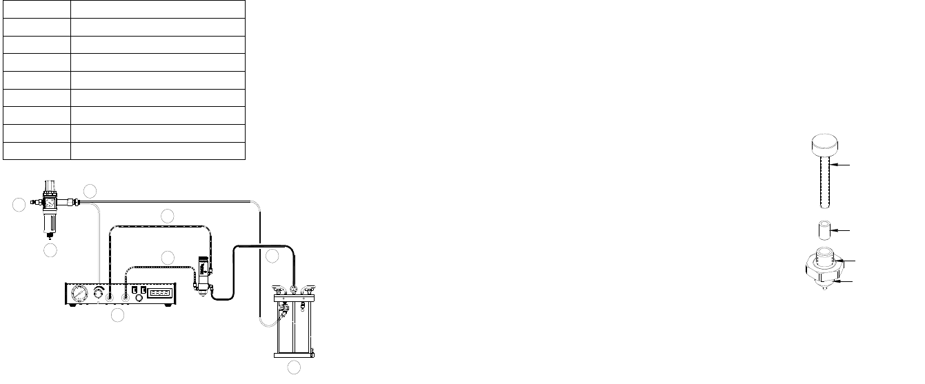
4. 밸브 연결
5. 작동 지침
1. 밸브 제어기에서 밸브 공기압을 70 psi(48 bar)로 설정하십시오.
2. 분사되는 유체의 점도에 따라 밸브 제어기에서 분사 공기압을
설정하십시오.
3. 분사되는 유체의 점도에 따라 유체 저장소의 유압을 설정하십시오.
100 psi(69 bars)를 넘지 않도록 하십시오.
4. 쓰레기통을 밸브 분사 노즐 아래에 놓고 유체가 계속 흘러나올 때까지
밸브를 비우십시오.
분사 범위는 다음과 같은 사항에 따라 결정됩니다.
• 행정 제어 조정 – 행정 제어 조정 손잡이를 시계 방향으로
돌리면 유속이 느려지고 시계 반대 방향으로 돌리면
빨라집니다. 손잡이 축에 표시된 '표시선' 너머로 손잡이를
돌리지 마십시오.
• 밸브 제어기에 설정된 가동 시간('밸브 온'시간)
• 유체 저장소의 압력
• 유체 점도
• 분사 노즐과 분사되는 표면 사이의 거리
항목 번호 내용
1 공기 유입구
2 공기 필터(옵션)
3 일정한 공기 흐름
4 밸브 공기 호스(포함)
5 분사 공기 호스(포함)
6 유체 공급 호스(옵션)
7 유체 저장소(TS1258 – 옵션)
8 밸브 제어기(TS500R – 옵션)
그림 2.0
MODE/TIME DISPLAY
MODE DECIMAL
MODE/TIME SET
1
2
7
8
4
5
6
3
TS5540
9
7.4 Seat Replacement (See Fig. 4.0 )
1. Insert the Thumb Screw inside the Nozzle (9) and rotate clockwise to attach
to the Seat (10).
2. Secure the Nozzle on a “soft jaw” vise and then pull the Thumb Screw, with
the Seat attached, straight out.
3. Install the new Seat on the Thumb Screw and then insert the Thumb Screw
straight into the Nozzle. To ensure proper seat alignment, it is recommended
that the seat installation is done on an Arbor Press.
8. SPARE PARTS AND ACCESSORIES
For TS5540/TS5540F spare parts and accessories information, please visit the
TS5540/TS5540F User Guide webpage at
http://www.techconsystems.com/literature/lit_manuals.cfm
9. LIMITED WARRANTY
OK International warrants this product to the original purchaser for a period of
one (1) year from date of purchase to be free from material and workmanship
defects but does not warrant normal wear-and-tear and damage to the
equipment as result of abuse and faulty installation. Defective product or
subassembly and components under warranty will be repaired or replaced
(at OK International's option) free of charge. Customer with defective product
under warranty must contact the nearest OK International office or distributor
to secure a return authorization prior to shipping the product to the assigned
OK International authorized service center. For nearest OK International office
or distributor contact information, please visit www.techconsystems.com. OK
International reserves the right to make engineering product changes without
notice.
Nozzle
Seat
Thumb Screw
O-ring
Figure 4.0