i3070+s5i_ReplacePowerSupply+ed2.pdf.pdf - 第13页
i3070 Lean Inline System (E9988EL) Replacing the Power Supply 13 8 Mount the bracket for the new Omro n 20 A AC/DC power supply. 9 Fit the new Omr on 20 A A C/DC power supply into the DIN rail and lock it. 10 Cables labe…
12 Replacing the Power Supply
i3070 Lean Inline System (E9988EL)
Installing the Omron 20 A AC/DC power supply
If installing the Omron 20 A AC/DC power supply, follow step 6 through step 15.
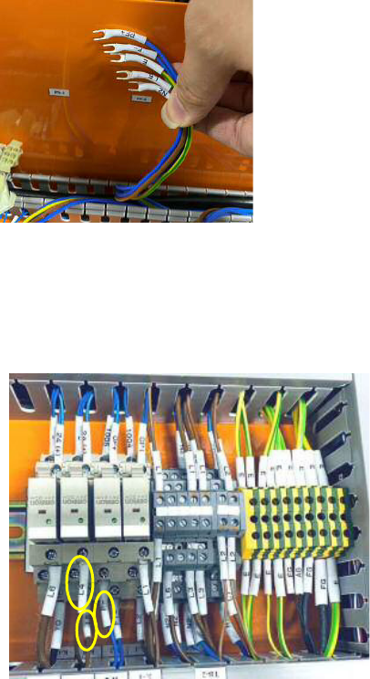
6 Locate and remove the cables labeled PF+, F-, E, L5 and N2 that were
connected to PS2, as they are no longer needed.
7 Locate and remove these cables:
• cable labeled F– that connects K-2 (terminal contact 12) and TB-4.
• brown cable labeled L4 that connects K-B (terminal contact 12) and F-4.
• brown cable labeled L5 that connects K-B (terminal contact 8) and TB-2.
i3070 Lean Inline System (E9988EL)
Replacing the Power Supply 13
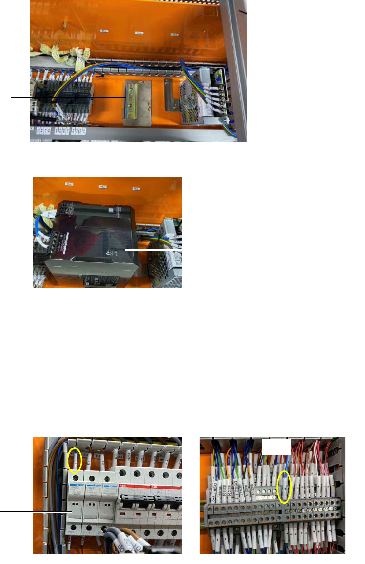
8 Mount the bracket for the new Omron 20 A AC/DC power supply.
9 Fit the new Omron 20 A AC/DC power supply into the DIN rail and lock it.
10 Cables labeled L1, N2, E, +, and – (previously connected to PS1) are to be
connected to the Omron power supply. The terminal point connections remain
the same.
• If using the existing cables, the connector heads have to be replaced with
ferrule heads to connect to the Omron power supply.
• If the existing cables are not long enough, replace them with the new cables
that have the same labels. Be sure to connect the new cables to the same
locations as the old cables.
11 Connect a new cable labeled + from F-5 to TB-4.
Mounting bracket for
Omron power supply
Omron 20 A AC/DC power supply
TB-4
F-5
14 Replacing the Power Supply
i3070 Lean Inline System (E9988EL)
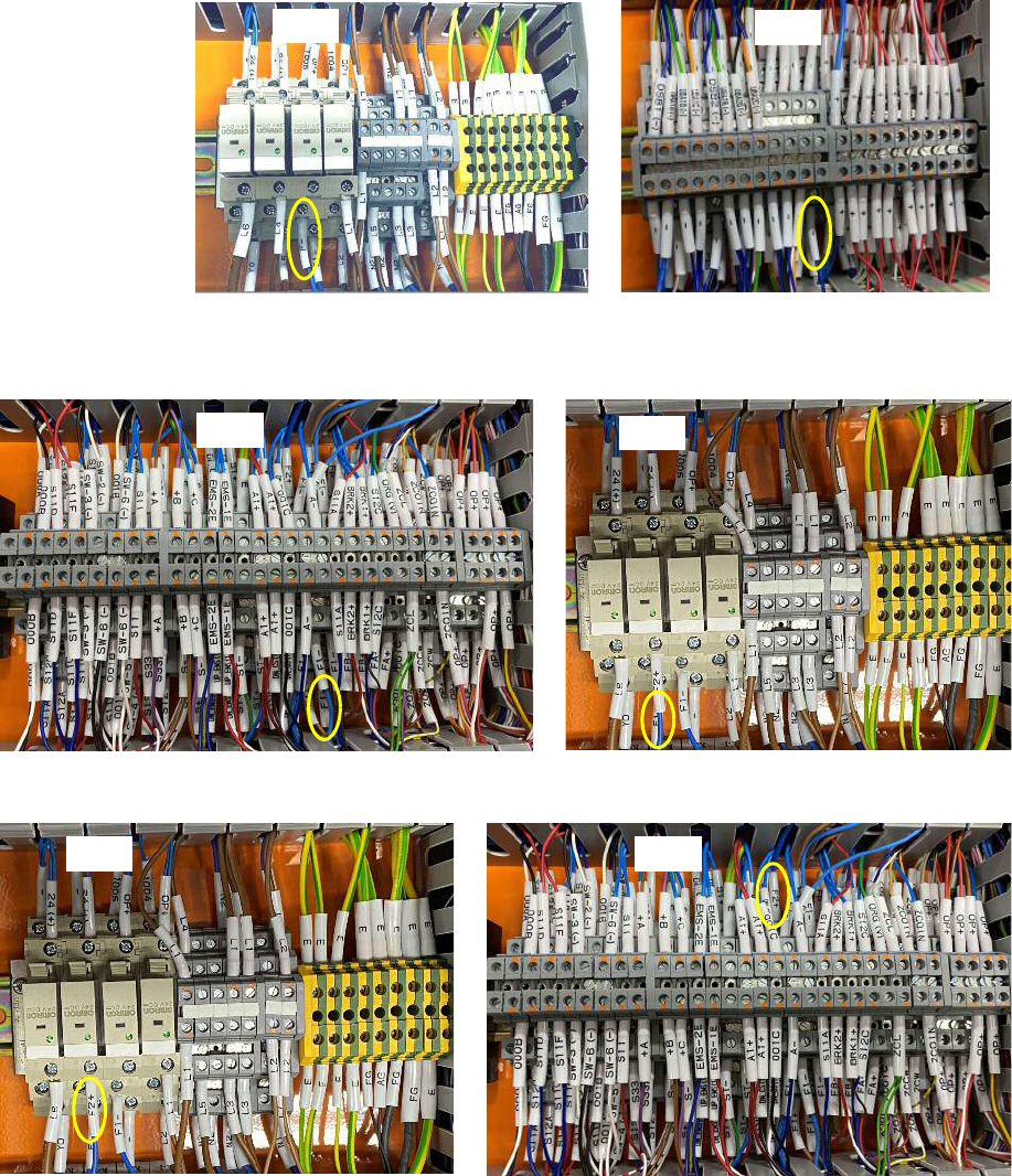
12 Connect a new cable labeled – from K-2 (terminal contact 12) to TB-4.
13 Disconnect the blue cable labeled F1+ from TB-3 and connect it to K-B
(terminal contact 8).
14 Connect a new cable labeled F2+ from K-B (terminal contact 12) to TB-3.
TB-4
K-2
TB-3
K-B
TB-3K-B