i3070+s5i_ReplacePowerSupply+ed2.pdf.pdf - 第20页
20 Replacing the Power Supply i3070 4-mod Inline System (E9986E) 11 Locate the cabl e labeled F1+ ( TB-2 to F-5). Disconnect the cabl e fr om TB-2 and connect it to K -B. 12 Connect a new cable labeled F2+ to K -B. Conne…
i3070 4-mod Inline System (E9986E)
Replacing the Power Supply 19
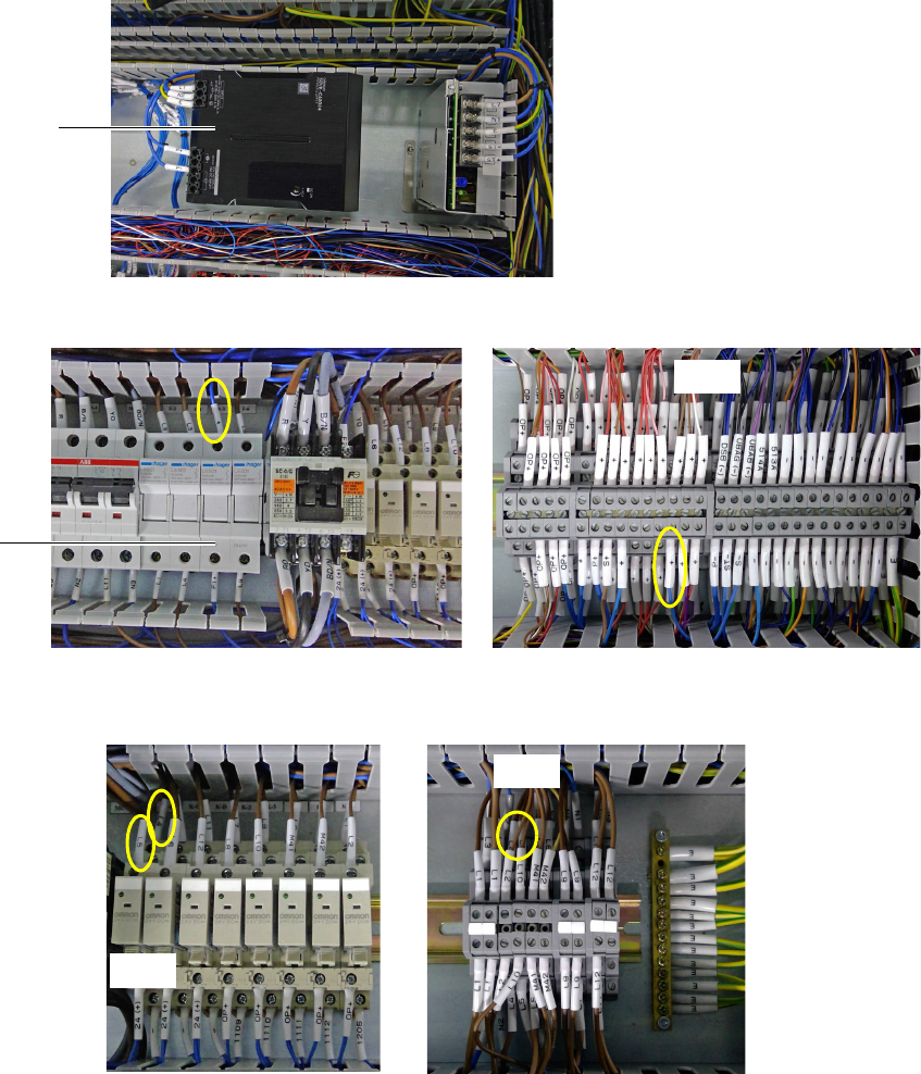
8 Cables labeled L1, N2, E, P+, and P- (previously connected to PS1) are to be
connected to the Omron power supply. The terminal point connections remain
the same.
• If using the existing cables, the connector heads have to be replaced with
ferrule heads to connect to the Omron power supply.
• If the existing cables are not long enough, replace them with the new cables
that have the same labels. Be sure to connect the new cables to the same
locations as the old cables.
9 Connect a new cable labeled + from F-5 to TB-3.
10 Remove the cables labeled L4 and L5 which are connected between K-B and
TB-1.
Omron 20 A AC/DC
power supply
TB-3
F-5
TB-1
K-B
20 Replacing the Power Supply
i3070 4-mod Inline System (E9986E)
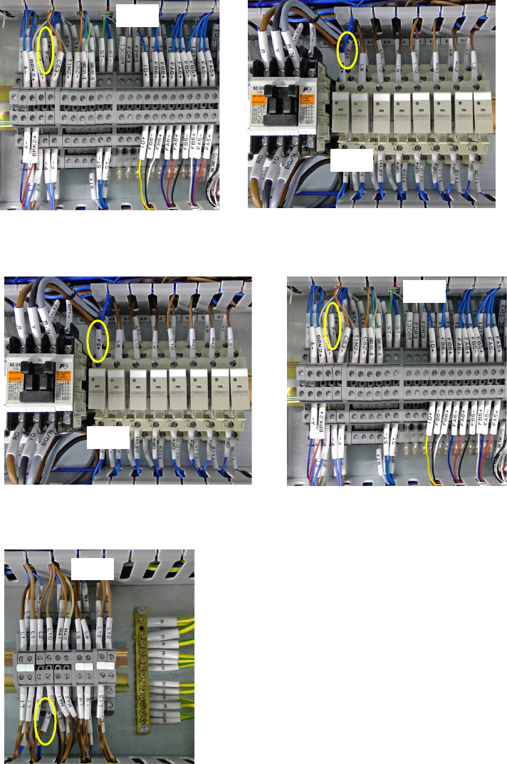
11 Locate the cable labeled F1+ (TB-2 to F-5). Disconnect the cable from TB-2
and connect it to K-B.
12 Connect a new cable labeled F2+ to K-B. Connect the other end to TB-2, in the
space previously occupied by F1+.
13 At TB-1, move the cable labeled L4 to the space previously occupied by L5
which was removed in step 5.
TB-2
K-B
TB-2
K-B
TB-1
i3070 4-mod Inline System (E9986E)
Replacing the Power Supply 21
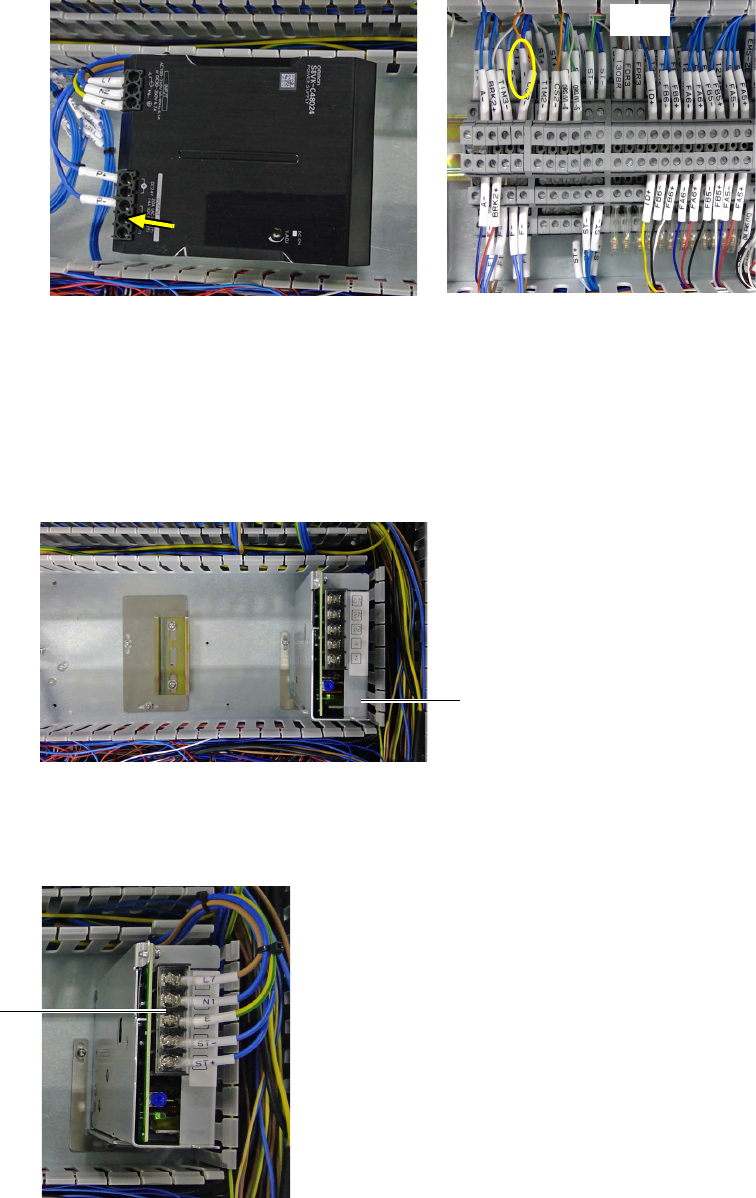
14 Connect a new cable labeled – from the Omron power supply to TB-2.
Proceed to Completing the installation.
Installing the Cosel 6.4 A AC/DC power supply
If installing the Cosel 6.4 A AC/DC power supply, follow step 15 through step 18.
15 Install the bracket and mount the new Cosel 6.4 A AC/DC power supply.
16 Connect the cables labeled ST+, ST-, E, N1, L7 (formerly from PS3) to the
Cosel power supply. Tighten the screws to secure the cables and close the
protective cover.
TB-2
Cosel 6.4 A AC/DC power
supply with bracket
protective cover