i3070+s5i_ReplacePowerSupply+ed2.pdf.pdf - 第6页
6 Replacing the Power Supply i3070 Inline System (E9988E) 4 Rem ove th e t ru nk in g c ove rs to access the cables. Installing the Omr on 20 A AC/DC power suppl y If installing the Omr on 20 A A C/DC power supply, follo…
i3070 Inline System (E9988E)
Replacing the Power Supply 5
i3070 Inline System (E9988E)
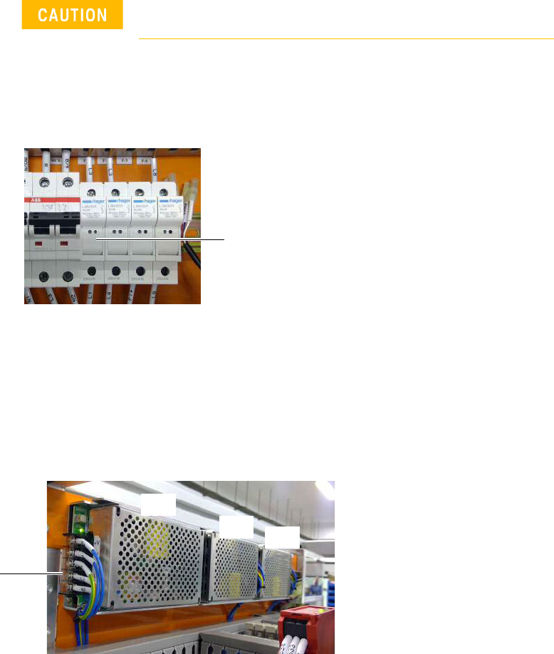
1 Remove the button screws securing the system’s top cover and remove the top
cover.
2 Open the F-3 fuse holder and replace the 2.5 A slow blow fuse with a new 6.0 A
slow blow fuse.
3 Remove old power supply:
If installing the Omron 20 A AC/DC power supply, remove PS1 and PS2.
If installing the Cosel 6.4 A AC/DC power supply, remove PS3.
a Open the protective cover and loosen the screws to release all cables at the
AC/DC power supply terminal point of the power supply to be replaced.
b Remove the button screws and any cable ties securing the power supply to
be replaced. Remove the power supply and bracket.
Turn off the main switch before beginning any replacement
work.
F-3
protective cover
PS1
PS3
PS2
6 Replacing the Power Supply
i3070 Inline System (E9988E)
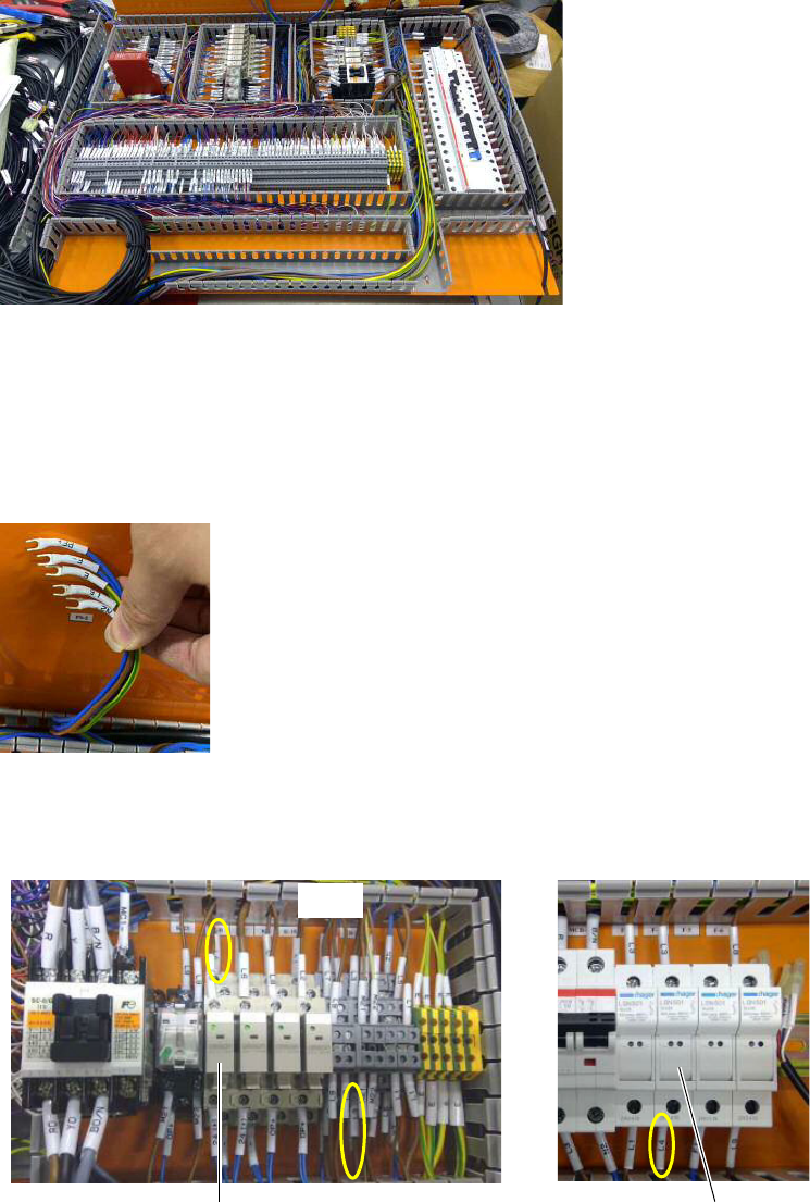
4 Remove the trunking covers to access the cables.
Installing the Omron 20 A AC/DC power supply
If installing the Omron 20 A AC/DC power supply, follow step 5 through step 13.
5 Locate and remove the cables labeled PF+, F-, E, L5 and N2 that were
connected to PS2, as they are no longer needed.
6 Locate and remove these cables:
• brown cable labeled L4 that connects F-4 and K-B (terminal contact 4).
• brown cable labeled L5 that connects TB-2 and K-B (terminal contact 3).
TB-2
K-B F-4
i3070 Inline System (E9988E)
Replacing the Power Supply 7
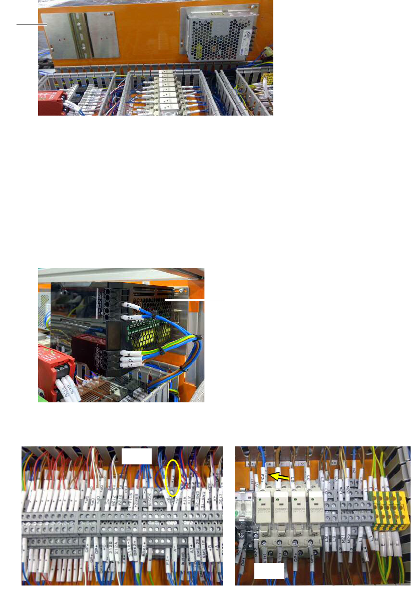
7 Mount the bracket for the new Omron 20 A AC/DC power supply.
8 Fit the new Omron 20 A AC/DC power supply into the DIN rail and lock it.
9 Cables labeled L1, N2, E, P+, and P- (previously connected to PS1) are to be
connected to the Omron power supply. The terminal point connections remain
the same.
• If using the existing cables, the connector heads have to be replaced with
ferrule heads to connect to the Omron power supply.
• If the existing cables are not long enough, replace them with the new cables
that have the same labels. Be sure to connect the new cables to the same
locations as the old cables.
10 Locate the cable labeled F1+ (TB-1 to F-5). Disconnect the cable from TB-1
and connect it to K-B (terminal contact 4).
Mounting bracket for
Omron power supply
Omron 20 A AC/DC power supply
TB-1
K-B