TM2939.Solder Remaining Quantity Detection-Function.pdf - 第15页
SMT Software En gineering G roup IM Operati ons Y AMAHA MOTOR CO., L TD. MDOC-SOFT50 128 15 /18 Fig.4.1 1 [Moni tor] - [So lder Transition] screen 4.3.3. Inspection result analysis graph Since th e solder f ill am ount m…
SMT Software Engineering Group
IM Operations YAMAHA MOTOR CO., LTD.
MDOC-SOFT50128
14/18
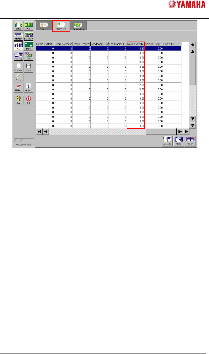
Fig.4.10 [MIS] - [Board Log] screen
4.3.2. Solder transition graph
Transition of the rolling width per board is displayed visually in [Monitor] – [Solder transition].
The horizontal axis is the number of produced board and the vertical axis is the rolling width. The
blue line shows rolling width scan result, the red line shows the ”Error Rolling Width” of board
data, and the green line shows the ”Warning Rolling Width” of the board data.
When solder is supplied (“Yes” button is tapped in “Ea8988:Supply Solder” message), the
“Supply” flag is indicated on the graph to check solder supply timings at a glance.
SMT Software Engineering Group
IM Operations YAMAHA MOTOR CO., LTD.
MDOC-SOFT50128
15/18
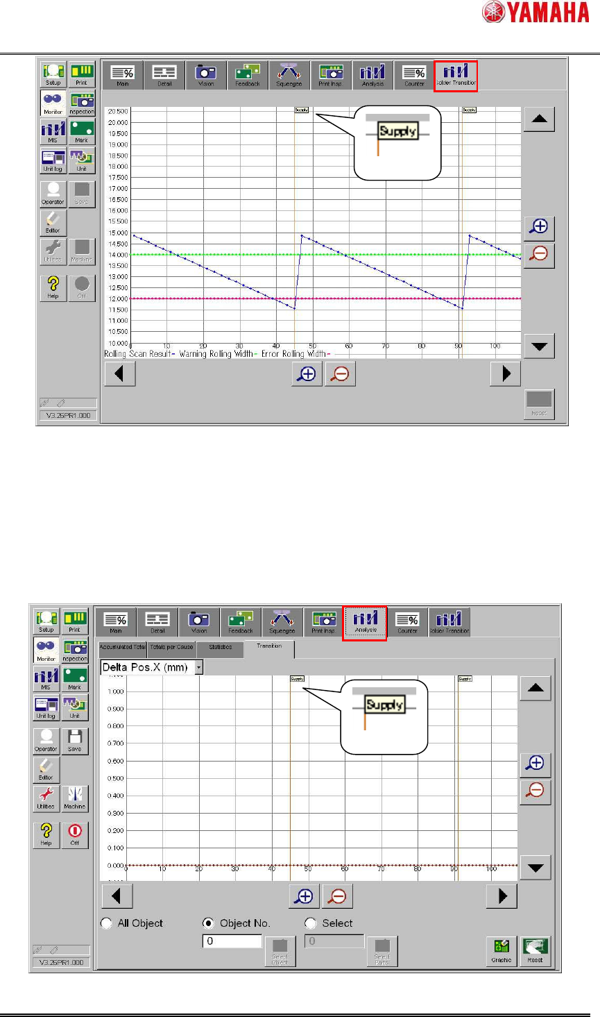
Fig.4.11 [Monitor] - [Solder Transition] screen
4.3.3. Inspection result analysis graph
Since the solder fill amount may vary as the solder is supplied, this change may affect the
inspection result. To make it easy to determine whether the effect depends on solder supply, the
“Supply” flag is indicated on the transition graph of the inspection result analysis to check the
solder supply timings at a glance.
Fig.4.12 [Monitor] - [Analysis] - [Transition] screen
“Supply” flag
“Supply” flag

SMT Software Engineering Group
IM Operations YAMAHA MOTOR CO., LTD.
MDOC-SOFT50128
16/18
5. Limitations
1. This function is specially designed only for the “3S head” of the printer YSP.
2. This function is not applicable to the printer board data in the text format. The board data
must be saved in the YGZ format.
3. If the board data is saved in the conventional printer “YGP”, the “Solder Remaining Quantity
Detection” parameters may be initialized. Upgrade the software to compliant version of the
“Solder Remaining Quantity Detection” function.
4. When editing the “Solder Remaining Quantity Detection” parameters in the Y.Fact Editor,
upgrade the software to compliant version of the “Solder Remaining Quantity Detection”
function.
5. This function is applied for metal mask only. Plastic mask and mesh mask are unusable.
6. The solder rolling width on the mask is scanned on the front side (after backward printing,
before forward printing) only; it is not scanned on the rear side (after forward printing, before
backward printing). This is because “Solder Scan Sensor” is mounted to the rear side of “3S
Squeegee Head”, if the rolling width is scanned on the rear side, the squeegee is located
over aperture of the mask, and adhered solder to the squeegee might be dropped on
aperture.
7. When “Round” printing is set in the board data, print cycle time might be increased because
the solder width is scanned on the way of round printing. In this case, “Ea8984: Print Cycle
Time Might Increase” message is displayed when auto-running is started.
8. This function cannot check whether solder amount is overmuch (rolling width exceeds a
certain threshold width).
9. The scanning distance of rolling width is decided by “Rolling Stroke” and “Over Stroke” of
board data. When the rolling width scan fails because the scanning distance is short, widen
the gap between "Rolling Stroke" and "Over Stroke".
10. When using this function, existing “Solder Supply Stop” function becomes invalid.
11. When using this function, auto-supplying solder function of “PSC (Print Stability Control)”
becomes invalid. However, when the machine equips with “PSC (Print Stability Control)”,
set ”PSC (Print Stability Control)” to ”Syringe Type” or ”Pot Type”, without invalidating it.
(Because safety checks of FX-axis becomes effective.)