TM2939.Solder Remaining Quantity Detection-Function.pdf - 第17页
SMT Software En gineering G roup IM Operati ons Y AMAHA MOTOR CO., L TD. MDOC-SOFT50 128 17 /18 6. Appen dix 6.1. Solder Remaining Quantity Detection Setting The details of the “Sol der Rem aining Q uantity Detec t ion” …

SMT Software Engineering Group
IM Operations YAMAHA MOTOR CO., LTD.
MDOC-SOFT50128
16/18
5. Limitations
1. This function is specially designed only for the “3S head” of the printer YSP.
2. This function is not applicable to the printer board data in the text format. The board data
must be saved in the YGZ format.
3. If the board data is saved in the conventional printer “YGP”, the “Solder Remaining Quantity
Detection” parameters may be initialized. Upgrade the software to compliant version of the
“Solder Remaining Quantity Detection” function.
4. When editing the “Solder Remaining Quantity Detection” parameters in the Y.Fact Editor,
upgrade the software to compliant version of the “Solder Remaining Quantity Detection”
function.
5. This function is applied for metal mask only. Plastic mask and mesh mask are unusable.
6. The solder rolling width on the mask is scanned on the front side (after backward printing,
before forward printing) only; it is not scanned on the rear side (after forward printing, before
backward printing). This is because “Solder Scan Sensor” is mounted to the rear side of “3S
Squeegee Head”, if the rolling width is scanned on the rear side, the squeegee is located
over aperture of the mask, and adhered solder to the squeegee might be dropped on
aperture.
7. When “Round” printing is set in the board data, print cycle time might be increased because
the solder width is scanned on the way of round printing. In this case, “Ea8984: Print Cycle
Time Might Increase” message is displayed when auto-running is started.
8. This function cannot check whether solder amount is overmuch (rolling width exceeds a
certain threshold width).
9. The scanning distance of rolling width is decided by “Rolling Stroke” and “Over Stroke” of
board data. When the rolling width scan fails because the scanning distance is short, widen
the gap between "Rolling Stroke" and "Over Stroke".
10. When using this function, existing “Solder Supply Stop” function becomes invalid.
11. When using this function, auto-supplying solder function of “PSC (Print Stability Control)”
becomes invalid. However, when the machine equips with “PSC (Print Stability Control)”,
set ”PSC (Print Stability Control)” to ”Syringe Type” or ”Pot Type”, without invalidating it.
(Because safety checks of FX-axis becomes effective.)
SMT Software Engineering Group
IM Operations YAMAHA MOTOR CO., LTD.
MDOC-SOFT50128
17/18
6. Appendix
6.1. Solder Remaining Quantity Detection Setting
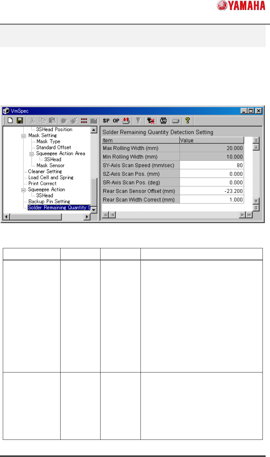
The details of the “Solder Remaining Quantity Detection” function are set in [Machine] -
[Setting] - [Machine Data] - [Solder Remaining Quantity Detection Setting]. Generally, don’t
change these values.
Fig.6.1 “Solder Remaining Quantity Detection Setting”
Table6.1 “Solder Remaining Quantity Detection Setting” items
Item Initial value
Input range
Explanation
Max Rolling Width
(mm)
20.000
0.000
~99.999
This parameter is the input maximum
value of ”Warning Rolling Width”
and ”Error Rolling Width” in a board data.
When input value is over “Max Rolling
Width”, “Ea8981:Data Check Error” is
displayed.
[NOTE] If this value is over 20.000mm, the
rolling solder spreads to the whole
squeegee and might not be formed rolling
shape uniformly.
Min Rolling Width
(mm)
10.000
0.000
~99.999
This parameter is the input minimum value
of ”Warning Rolling Width” and ”Error
Rolling Width” in a board data.
When input value is less than “Min Rolling
Width”, “Ea8982:Data Check Error” is
displayed.
SMT Software Engineering Group
IM Operations YAMAHA MOTOR CO., LTD.
MDOC-SOFT50128
18/18
[NOTE] If this value is less than
10.000mm, the rolling solder rises with the
squeegee and might not be able to print
correctly.
SY-axis Scan
Speed (mm/sec)
80
0~999 This parameter is the movement speed of
SY-axis in case of scanning the rolling
width.
SZ-axis Scan Pos.
(mm)
0.000
-99.999
~99.999
This parameter is the height of SZ-axis in
case of scanning the rolling width.
SR-axis Scan
Pos. (deg)
0.000
0.000
~180.000
This parameter is the angle of SR-axis in
case of scanning the rolling width.
Rear Scan Sensor
Offset (mm)
-23.200
-999.999
~0.000
This parameter is the Y direction distance
from “Solder Scan Sensor” to the center of
SR-axis rotation.
Rear Scan Width
Correct (mm)
1.000
0.000
~99.999
This parameter is the correction value
added to the scanning result of the rolling
width.