00194398-01.pdf - 第39页
Retrofit instructions SIPLACE HS-60 12/2004 Edition 2.1 Overview 39 2.1.2 T ech nical dat a 2 2 2 2 2 2 2 2 2 2 2 2 2 2 2 2 2 2 Substrate format 50 mm x 50 mm to 100 mm x 178 mm Substrate thickness 0.5 mm to 1.5 mm Subst…
Retrofit instructions SIPLACE HS-60
2.1 Overview 12/2004 Edition
38
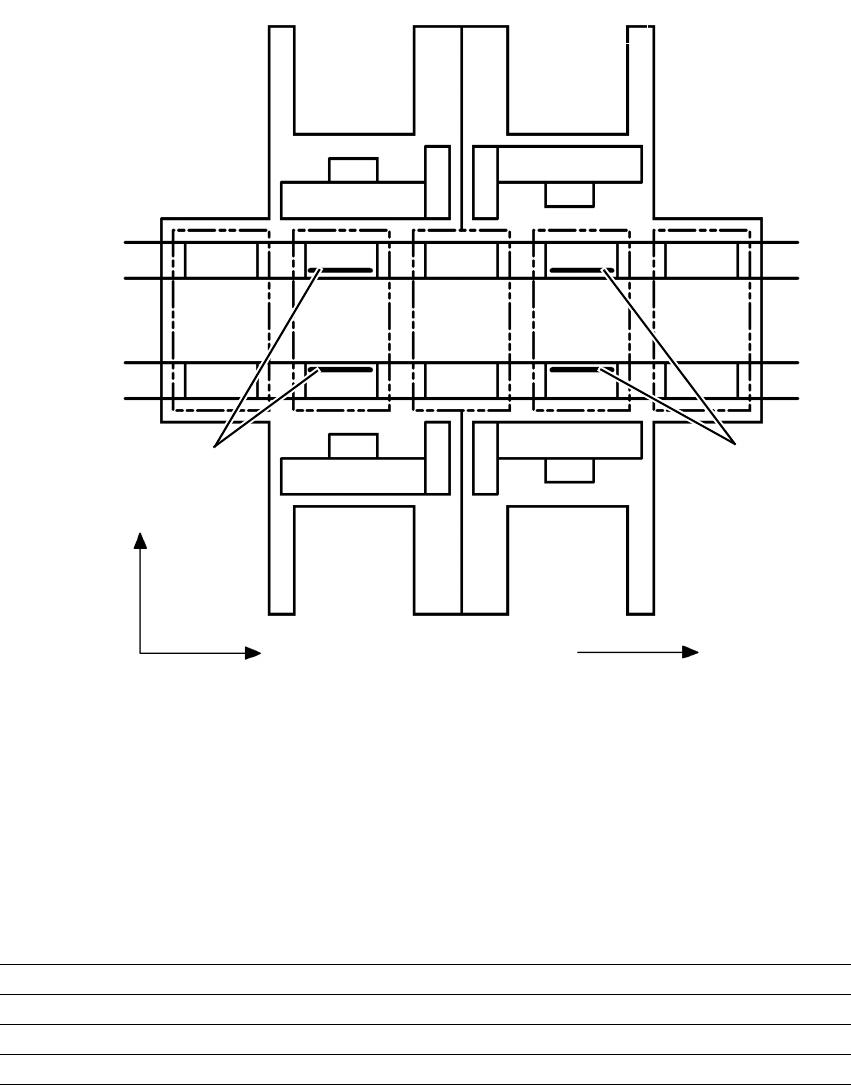
– The ceramic substrate centering option must be removed in order to convert from dual to single
conveyor.
Fig. 2.1 - 1 Arrangement of the ceramic substrate centering units, stationary conveyor side on the right.
2
2.1.1 Possible centering modes
The following centering modes for ceramic substrates may be entered under conveyor mode in
the machine data (real.ma).
2
Direction of transport
Input
area
Location 3
Location 1
Location 2
Gantry 4
Gantry 3
Gantry 2
Gantry 1
Conveyor 2
(left)
Conveyor 1
(right)
Location 4
Processing
area PC1
Intermediate
area
Processing
area PC2
Output
area
Mechanical
ceramic substrate
centering
Mechanical
ceramic substrate
centering
+Y
+X
43
12
Conveyor mode Centering
4 Mechanical substrate centering with normal lighting
5 Multicolor with Y axis clamping only
6 Mechanical ceramic substrate centering with multicolor

Retrofit instructions SIPLACE HS-60
12/2004 Edition 2.1 Overview
39
2.1.2 Technical data
2
2
2
2
2
2
2
2
2
2
2
2
2
2
2
2
2
2
Substrate format 50 mm x 50 mm to 100 mm x 178 mm
Substrate thickness 0.5 mm to 1.5 mm
Substrate finish unscribed (easy)
scribed (after testing)
Contact surface on conveyor belt 3 mm
Optical centering: field of vision of PCB vision module
Method of illumination for light pastes:
Method of illumination for dark pastes and short distance from
adjacent structures (> 1 mm)
5.7 mm x 5.7 mm
PCB vision module (standard)
Multicolor
Fiducial criteria See PCB vision module position detec-
tion
Mechanical centering:
X/Y centering accuracy ± 0.07 mm / 4 Sigma
PCB underside clearance 12 mm
Compressed air connection 0.5 MPa (5.0 bar)

Retrofit instructions SIPLACE HS-60
2.2 Safety instructions 12/2004 Edition
40
2.2 Safety instructions
WARNING
The safety instructions from the “Operational safety” chapter of the user manual and servicing in-
structions take precedence over these instructions. 2
The SIPLACE placement machines are supplied with mains voltage.
Consequently parts of these systems carry dangerous voltages! This voltage is present at certain
modules inside the machine base, even when the machine is switched off at the main power
switch.
Incorrect handling of the placement machine or touching live parts of the machine can result in
death or severe injury, and considerable damage to equipment.
BEFORE starting any work, shut down the operating system correctly, then switch the machine
OFF at the main power switch and disconnect from the main power supply. In addition, the com-
pressed air supply must be switched off at the compressed air unit's main valve in the machine
base and vented by actuating the needle valve on the compressed air unit.
There is DANGER for heart pacemaker wearers in the vicinity of the linear motors, as described
in detail in the "Special safety instructions for working in the vicinity of strong magnetic fields"
section of the user manual and service manual.
Always follow the accident prevention regulations, DIN or other standards and special safety
rules applicable in your country.
Pay attention to the information concerning residual voltages in the Operational Safety chapter.
Follow the ESD regulations as described in the operational safety section of the operating
instructions.
During the retrofit, always secure the machine to prevent access by other people and to prevent
it being switched on again. The procedure is described in the “Locking the machine…” section of
the user manual.
Working with the SITEST program further increases the risk of accident.
SITEST must only be used by authorized and trained personnel.
2
2.2.1 Definitions
2
PLEASE NOTE 2
2
2
2
Caution 2