00194398-01.pdf - 第45页
Retrofit instructions SIPLACE HS-60 12/2004 Edition 2.5 Mechanical conversion 45 : Disconnect the main co mpressed air supply to the lif ting tab les in placement area 1. 2 : Insert the T - piece provide d and the four-w…
Retrofit instructions SIPLACE HS-60
2.4 Preparatory work 12/2004 Edition
44
2.4 Preparatory work
2
The lifting table beds must be / remain lowered so that there is no strain on the terminal blocks.2
2
: Set the PCB conveyor to maximum width.
: Switch the placement machine off at the main switch.
2
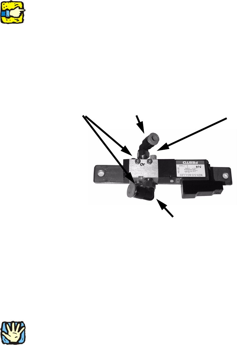
: Screw the solenoid valve onto the supporting plate using two screws (see photograph below).
The terminals of the solenoid valve are assigned as follows: 2
2
2.5 Mechanical conversion
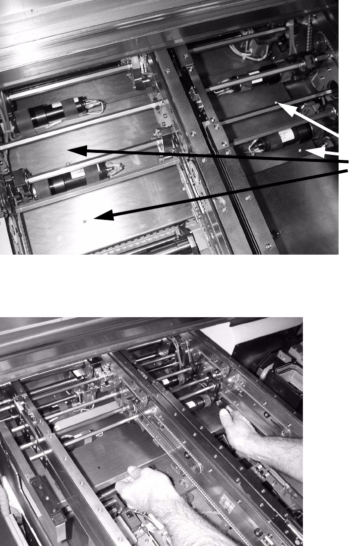
2.5.1 Replacing the lifting table beds
: Loosen and remove the 4 hexagon socket head screws used to fix the lifting table bed to the
lifting table unit.
2
There is a risk of crushing / cuts while lifting out the lifting table beds, particularly between the outer
edges of the lifting table bed and the conveyor modules. 2
See also pneumatic drawing in Section 2.8. 2
Compressed air outlet
Silencer
Compressed air inlet
Screws
Retrofit instructions SIPLACE HS-60
12/2004 Edition 2.5 Mechanical conversion
45
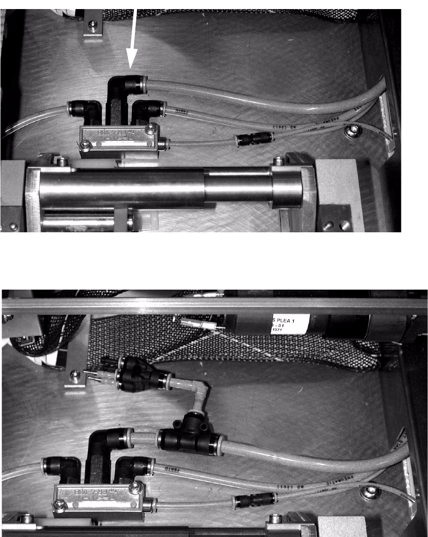
: Disconnect the main compressed air supply to the lifting tables in placement area 1.
2
: Insert the T-piece provided and the four-way or two-way distributor between the compressed
air line and main supply to the lifting tables, as shown in the picture.
2
2
2
Main compressed air supply to lifting tables
Retrofit instructions SIPLACE HS-60
2.5 Mechanical conversion 12/2004 Edition
46
: Loosen the six screws on the cover over the conveyor control conversion board, and push the
cover away.
2
2
: Remove the cover over the conversion board (6 screws).
. 2
2
2
Screws
in cover
of conveyor
control