00194398-01.pdf - 第59页
Retrofit instructions SIPLACE HS-60 12/2004 Edition 2.7 Adapting to the size of the substra te 59 : With the movab le stop, make sure that the pins eng age in the gr oove in the carriage unit. 2 Fig. 2.7 - 3 Ceramic subs…
Retrofit instructions SIPLACE HS-60
2.7 Adapting to the size of the substrate 12/2004 Edition
58
: Fit the necessary stop unit 1, 2 or 3 (see table above).
2
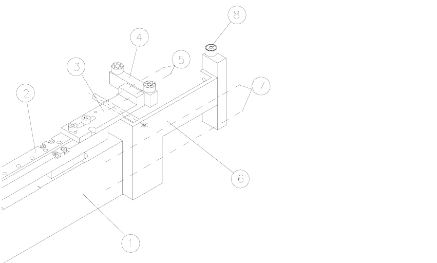
Fig. 2.7 - 2 Matching the ceramic substrate centering to the size of substrate
Key: 2
1. Base unit
2. X carriage unit
3. Fixing bracket for stop rail, 2 hexagon socket head screws M3 x 8
4. Stop rail (according to size of substrate: see table above)
5. 2 hexagon socket head screws M3
6. Stop unit with spacer bolt (according to size of substrate: see table above)
7. Fixing for stop unit: 2 hexagon socket head screws M3
8. Fixed stop roller
2
2
2
2
2
2
Retrofit instructions SIPLACE HS-60
12/2004 Edition 2.7 Adapting to the size of the substrate
59
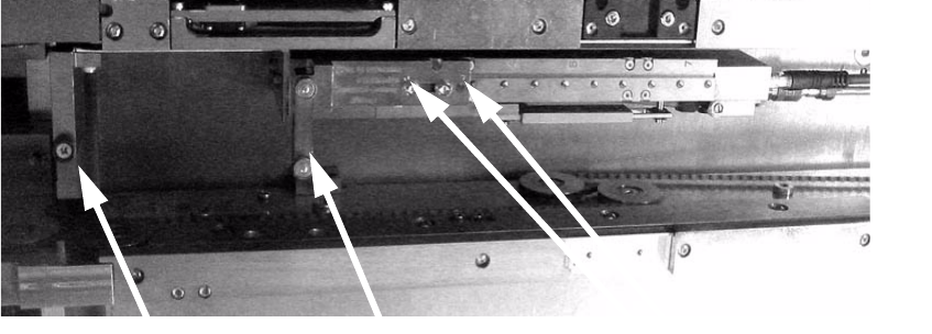
: With the movable stop, make sure that the pins engage in the groove in the carriage unit.
2
Fig. 2.7 - 3 Ceramic substrate centering (side view)
Fixed stop
Movable stop
Pins in the groove
Retrofit instructions SIPLACE HS-60
2.8 Pneumatic drawing 12/2004 Edition
60
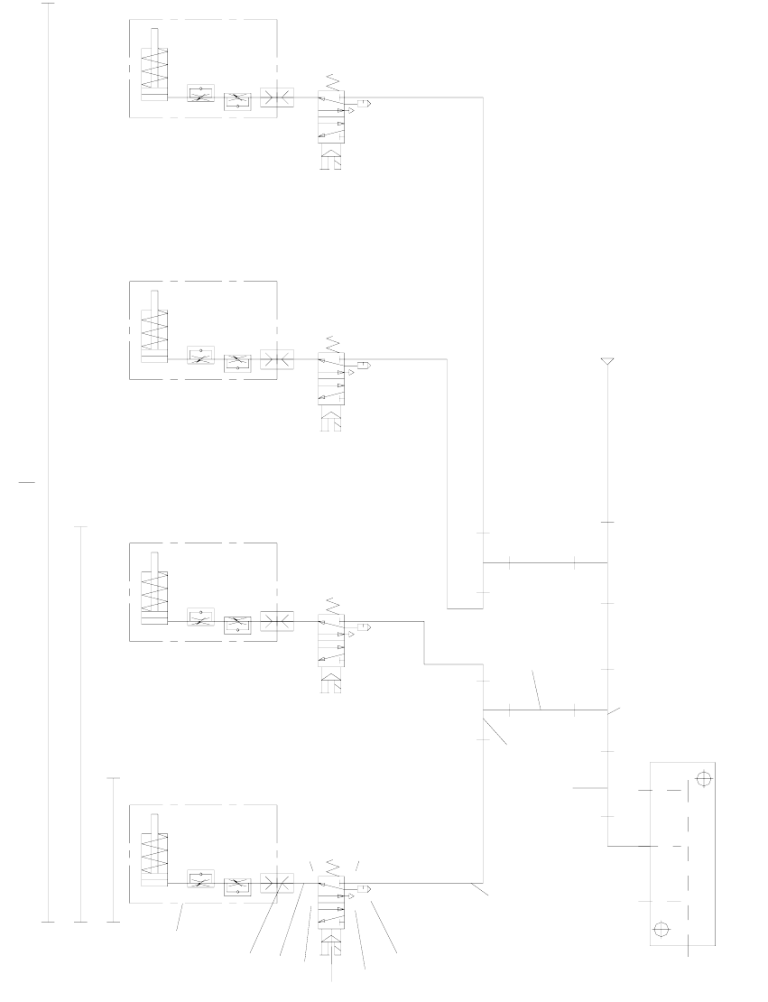
2.8 Pneumatic drawing
2
Fig. 2.8 - 1 Pneumatic drawing for ceramic substrate centering unit, HF series, HS-60, S-27 HM (00119671-010501)
Ø8x1.25
p=5.5 bar
Conveyor air distributor
10
10
5
9
8
7
6
6
5
4
3
2
1
HS60 DC + HF DC
S27HM DC + HS60 + HF
Ceramic substrate
centering assembly
5
1
4
3
2
5
1
4
3
2
5
1
4
3
2
5
1
4
2
3
Lock connections 4 and 5 using the item 10 screws.
S27HM